Week of the 09/14/2026 - #38
Contents
tech
- Sega Genesis Links
- DIY HIFI Audio
Sega Genesis Links
I noticed that my Sega Genesis is making a humming noise. I still haven’t figured out what is causing it. I need to do a deep dive on how the sound works on the Genesis and understand where the noise is coming from. It seems like low frequency so I’m guessing it could be some line noise that is creeping in. I went on a dive to get some information regarding the hardware and here are some useful links:
-
First order of business is to know what revision of the motherboard I have. After a little search here is a good page with all the different versions: Sega Mega Drive/Hardware revisions
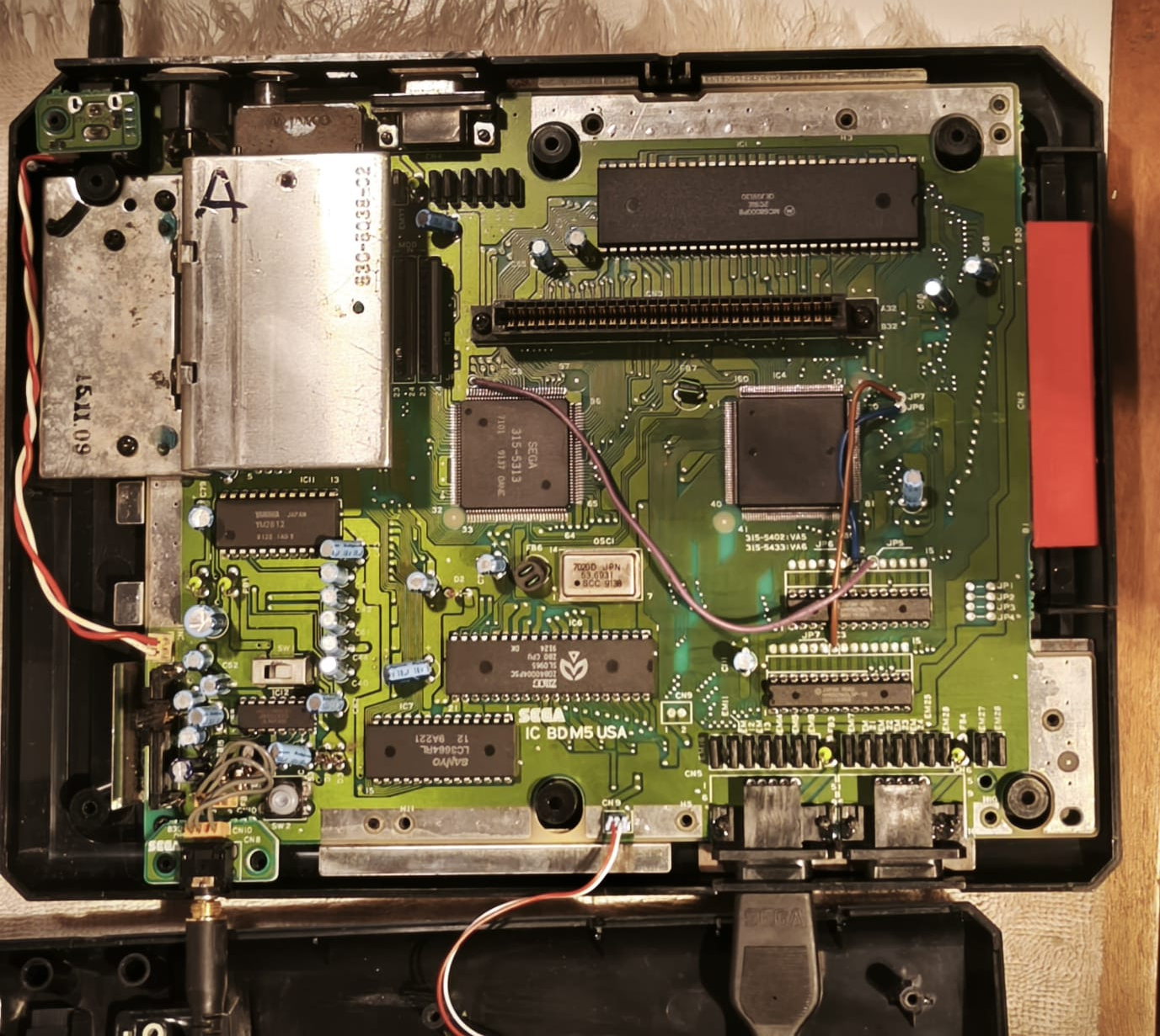 Sega Genesis Model 1 - V6
 -
The hardware would appear to be:
Components:
- M68K CPU: Motorola MC68000P8
- M68K memory: 2x HM652568LSP-10 (32Kx8 PSRAM, 100 ns)
- Z80 CPU: Zilog Z0840004PSC
- Z80 memory: MB8464A-10 (8Kx8 SRAM, 100 ns)
- I/O chip: Sega 315-5433
- VDP: Sega 315-5313 (Yamaha YM7101)
- Video RAM: 2x [NUMBER PLEASE] (64Kx4 DRAM)
- Headphone amp: Sony CXA1034
- Video encoder: Sony CXA1145P
- FM synthesizer: Yamaha YM2612
- Identical to VA5, but with TMSS implemented. This was also the first North American revision with TMSS on board.
- On some VA6 revisions, the unused female DE-9 port (used only by the Mega Modem in Japan) is removed.
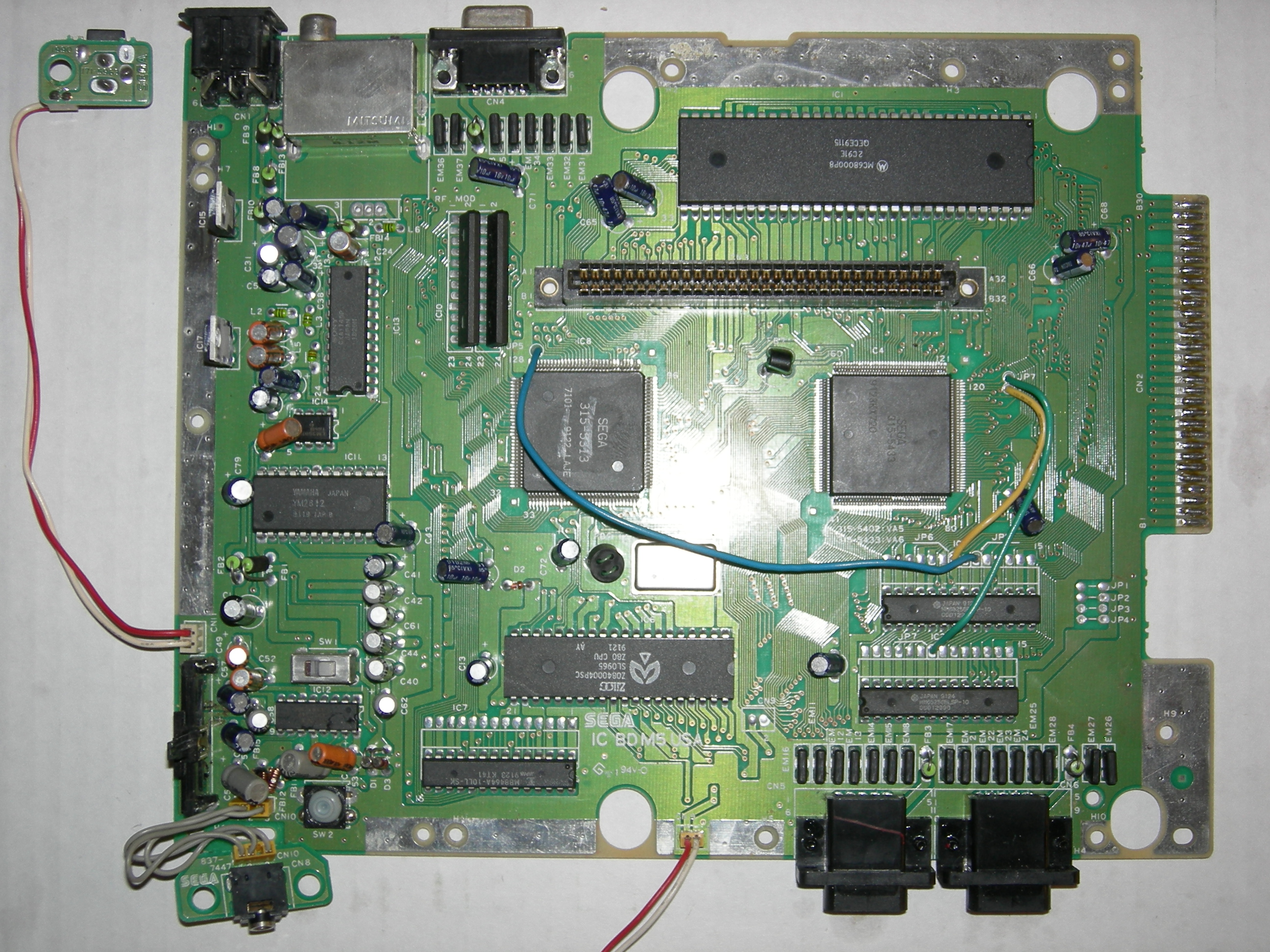 My Sega Genesis Model 1 - V6 with all components visible
- Audio Circuit Mod - Early revisions of the model 2 Genesis/Mega Drive, specifically the VA0, VA1 and VA1.8 boards, are known for their lower quality audio compared to most model 1s and even the later VA3 and VA4 model 2s. However, it is possible to improve the audio on these systems without resorting to a more invasive mod such as a Triple Bypass or Mega Amp. This can be done by swapping a few component values on four capacitors and resistors in the input stage, as well as swapping both op-amp chips. Additionally, a few passive components must be added as necessary. You can also perform a similar mod with VA7 model 1 units, as there are some similarities.
- Schematics for the Genesis PDF - A schematic of the Genesis Architecture.
Schematic for Sega Genesis PAL V6.5 console
From that page:
“The VA6.5 is simply a VA6 with the EXT port and its line filters removed, since the EXT port was unused in most markets. No other changes were made, though consoles with this board have a large blank space on the rear where the EXT port once was. The “VA6.5” name originates from Sega service documentation[13] and is not denoted on the board itself. Many of these used the 315-5313A or 315-5313A-01 VDP.”
also in regards to V6:
“Completely identical to the VA5 but substitutes the I/O chip with the 315-5433 (NEC uPD92271), which adds the TradeMark Security System (TMSS) lockout screen (“Produced by or Under License by Sega Enterprises, Ltd”) that appears for several seconds before playing any game. TMSS checks for the word “SEGA” at two locations in the game code, and if it is not at either one of these memory locations, the game will not run. TMSS would be present in all Genesis/Mega Drive consoles from this point forward.
In addition, the VA6 was the last board revision in most markets to have the EXT port. Sega had planned to release a modem which used this port, but it ultimately only saw a Japanese release (known there as the Mega Modem), and Sega abandoned their plans to release it elsewhere.
The VA6 first appeared in US Genesis consoles that were sold beginning in September 1991, with other regions following later that year. VA6 boards found in later Japanese Mega Drives used the revised 315-5313A VDP. In PAL regions, the VA6 is extremely uncommon and only appeared in certain Mega Drives produced in Japan during 1992 with a serial number starting with ‘A’ or ‘Q’”
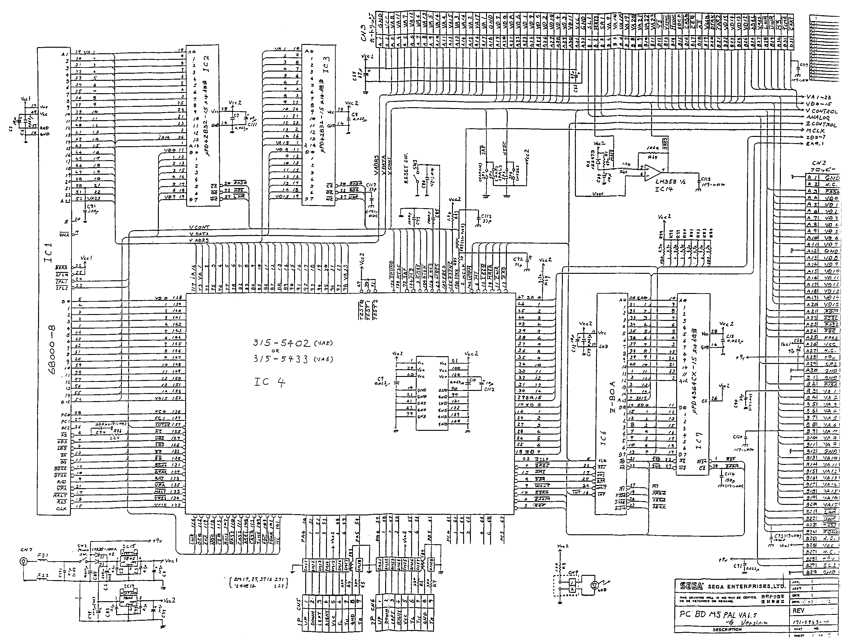
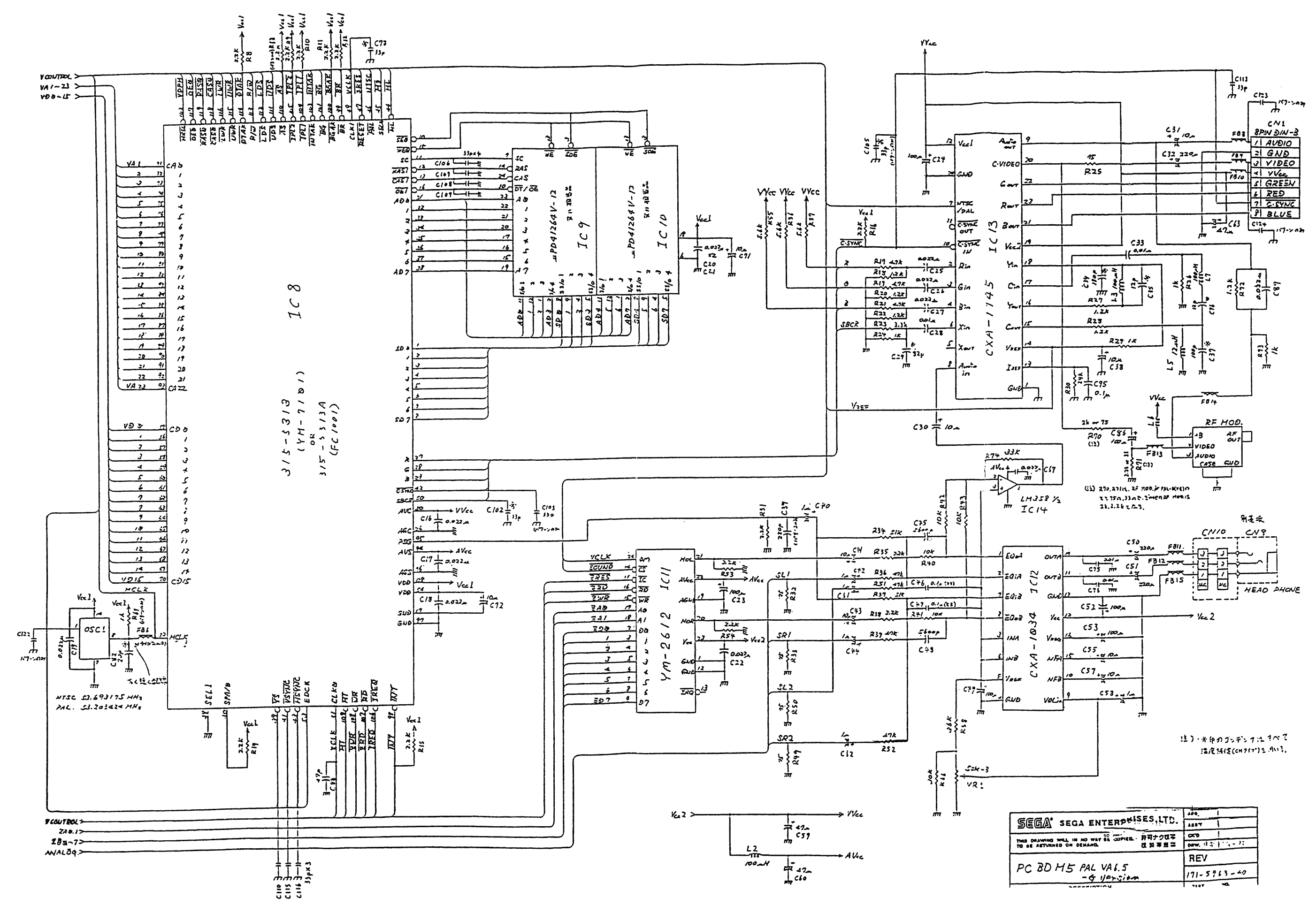
ICs
IC BD M5 USA VA6 (315-5483)
- IC1: CPU: MC68000P8
- IC2: SRAM: SRAM 256Kb: 32K x 8-bit TC51832SPL-10, MCM51L832ASP10, HM65256BLSP-10
- IC3: SRAM: SRAM 256Kb: 32K x 8-bit TC51832SPL-10, MCM51L832ASP10, HM65256BLSP-10
- IC4: 315-5433
- IC6: CPU: Z08400044PSC
- IC7: SRAM (Z80): KM6264BL-10
- IC8: 315-5313
- IC9: VRAM: VRAM 256Kb: 64K x 4-bit KM424C64Z-10, D41264V-12
- IC10: VRAM: VRAM 256Kb: 64K x 4-bit KM424C64Z-10, D41264V-12
- IC11: Audio Processor: YM2612
- IC12: Audio Amplifier: CXA1034P, AN7108
- IC13: RGB Encoder: CXA1145P
- IC14: HA17358
- IC15: +5V Regulator: 7805
-
IC17: +5V Regulator: 7805
- Audio Circuit (Sega Mega Drive) - This page has a good diagram of the audio circuit and a description of how it works. Since you have to log in to view it here’s the content:
Audio System Overview
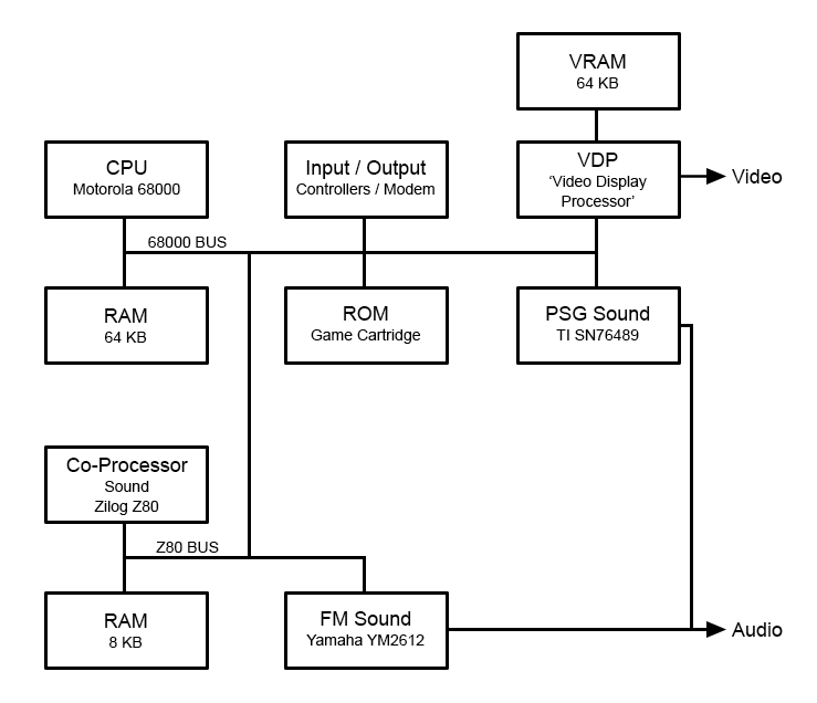
The Mega Drive has two main sources of sound. The FM syth and the PSG sound. Both get mixed together before forming the final audio that gets amplified and output.
FM Synthesis
All FM audio is produced via the Yamaha YM2612 FM synthesis chip.
The 68k processor generates the audio data, sends it to the Z80 co-processor, which then sends it on to the YM2612.
ℹ️
- In order for the two processors to communicate, and thereby produce digital audio to drive the YM2612, all of the inter-communication chips must be functioning.
- For VA0, VA1, and VA2 the IO Controller (315-5309) and Bus Arbiter (315-5308) and Clock Generator (315-5345) are used.
- On VA3 and VA4 it is done via the same IO Controller (315-5309) but the Bus Arbiter (315-5308) and Clock Generator (315-5345) are combined into a single chip (315-5364).
- On VA5, VA6, VA6.5 and VA6.8 this is done by combining both chips from the VA3/4 together into one. On VA5 it is 315-5402 and VA6 it is 315-5433 (on VA6) The only difference is the 315-5433 also contains the trademark screen TMSS ROM. These chips combine the IO Controller (315-5309) and Bus Arbiter/Clock Generator (315-5364)
- On VA7 all this functionality is combined into a single ASIC, the 315-5487.
PSG Audio
The PSG audio is a 4-channel Programmable Sound Generator capable of 3 wave form generators and 1 noise generator.
Technically it is done via the TI SN76489 chip. However on the Mega Drive this chip is directly integrated into the 315-5313 Video Display Processor (which is a Yamaha YM7101).
ℹ️
- On the VA7 models, both the FM and PSG audio is generated inside the single ASIC 315-5487.
- There is no PSG audio or YM2612 chips on the VA7, the audio simply comes straight out of the ASIC.
Audio Processor (Yamaha YM2612)
The YM2612 sound chip receives its data from the Z80, and outputs analog audio as Mono Left and Mono Right outputs.
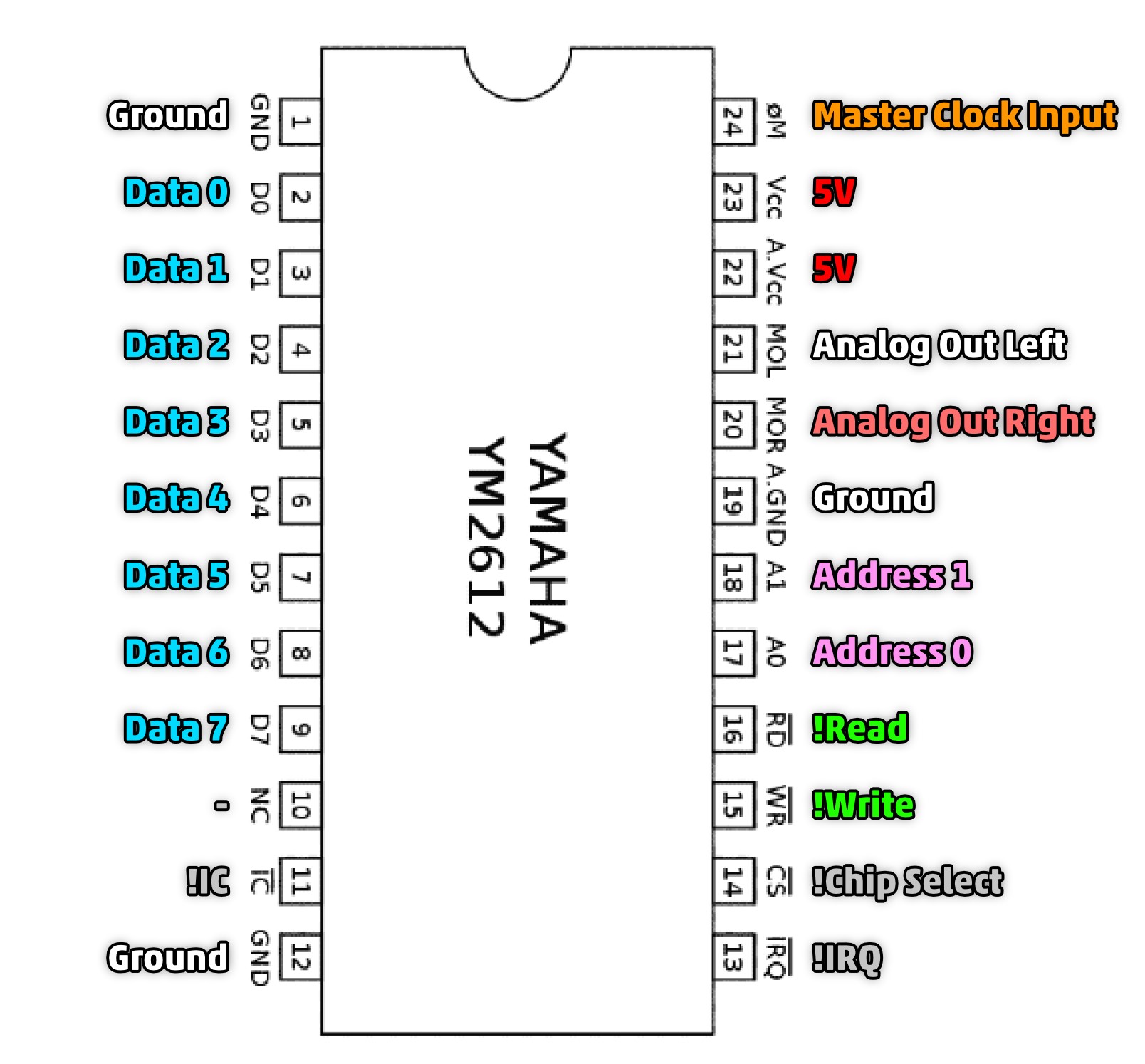
The output audio should be about a 1Vpp signal.
ℹ️
- If you don’t have an oscilloscope, you can probe the RCA audio jack wires for left or right audio directly onto the Analog Out pins of the YM2612 and you will hear the audio. It will be a little quite but you will definitely hear it.
Audio Mixing
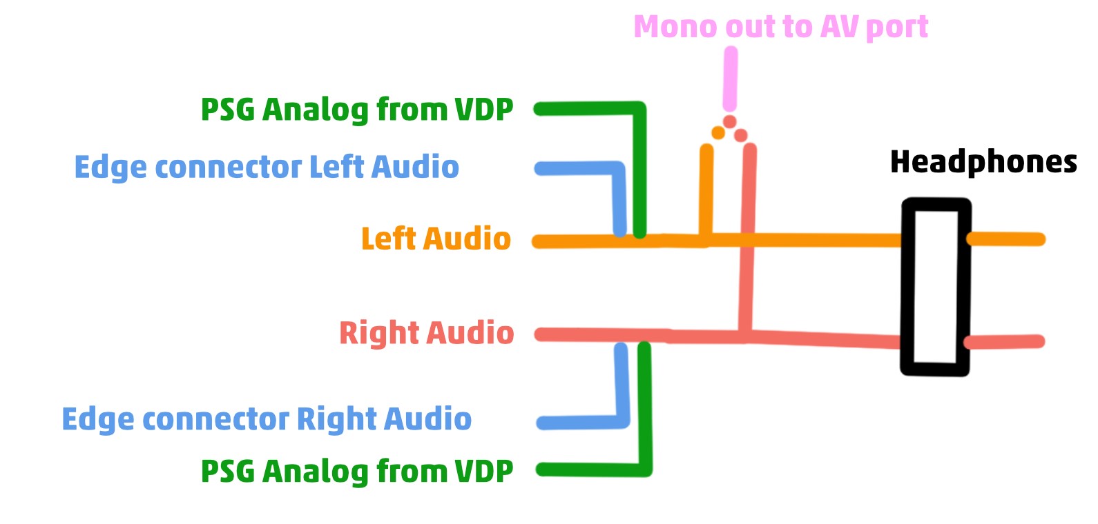
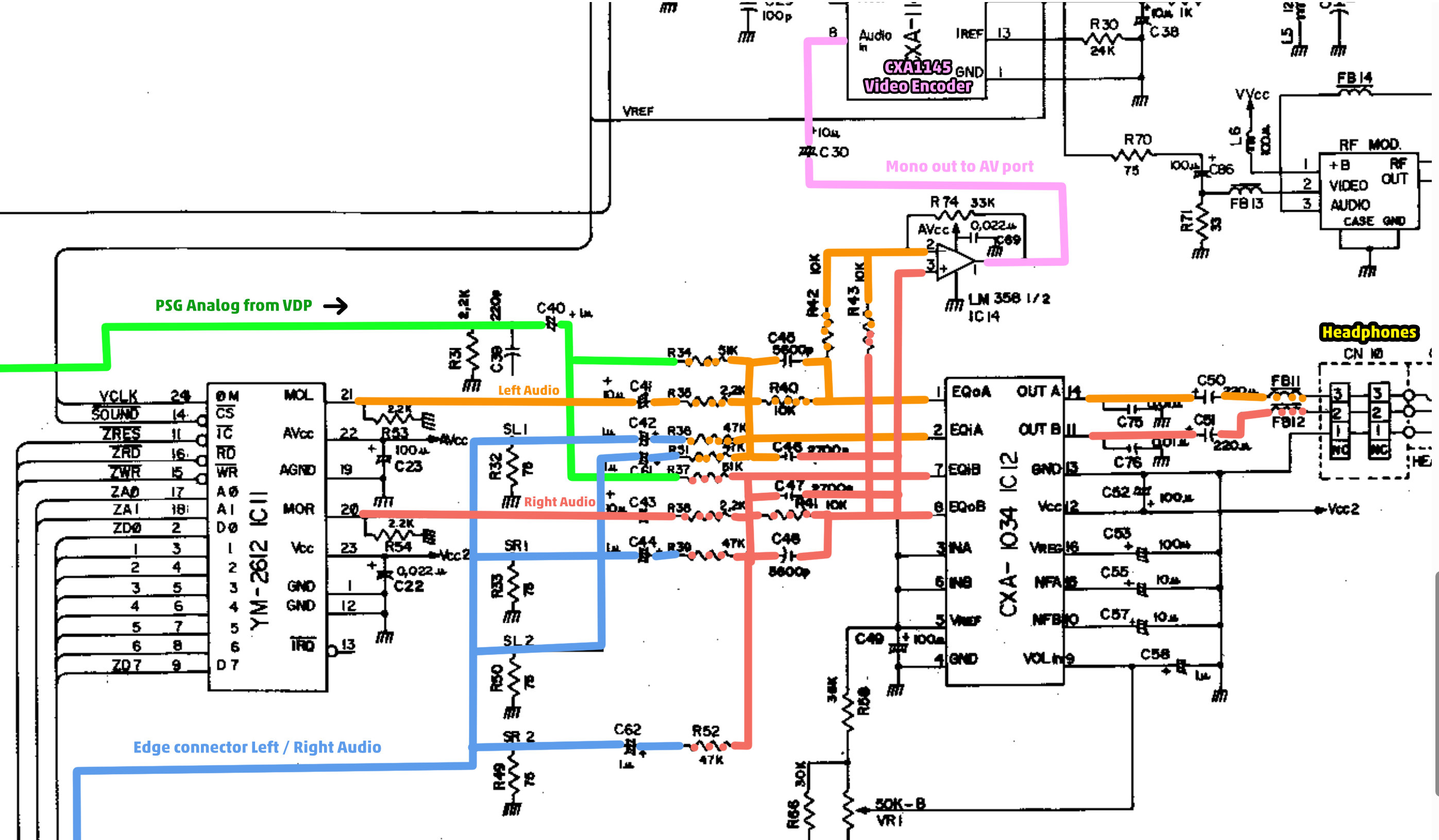
After the FM audio comes out of the YM2612 is when all the sources of audio get mixed together.
Firstly the edge connector SL2 (pin B29) SR2 (pin A29) mix any analog audio coming from the Mega CD connected to the edge connector, into the analog audio.
Secondly, the 315-5313 mixes its PSG analog audio output (pin 95) into both the left and right audio channels.
Finally this forms the full left and right audio signals. This is mixed to mono through the LM358 Op Amp and sent to the CXA1145 Video Encoder as Mono Audio to send out of the AV port.
The left and right channels are also sent through the Sony CXA1034 Headphone Amp and out to the headphone port.
Audio Amplifier (Sony CXA1034P)
The CXA1034P audio amplifier is used to output audio to the headphone port.
Crackling On Audio
I have seen a few times, if you get random crackling on the audio both headphone and AV port, like a radio static, it can be failing 7805 LDO regulators.
To confirm, join both outputs of the 7805 regulators together, then power the console from a bench power supply on the 5V outputs of the regulators, directly with 5V.
If the noise goes away, your regulators are bad and need replacing, or upgrading to a CleanPower USB-C mod.
DIY HIFI Audio
I’m thinking about building a DIY CD Player / ripper. The idea is to build a CD player using an old CD player from a computer, adding a Raspberry PI and a hi-fi DAC. A good DAC that I can get from Aliexpress is based off an ES9039Q2M. There are several options: for $27 - $50 USD you can get a board I2S digital audio input and a 3.5mm or RCA analog audio output. I would also include a dislpay (which could be a salvaged phone). My idea is also to have a SDD hard drive where I can store the ripped CDs and be able to show in the screen the album cover and use it as a media library. Nice to have is to have movies as well :-).
- Audio DIY Pinterest board - I created a Pinterst board with some nice Audio cabinet designs.
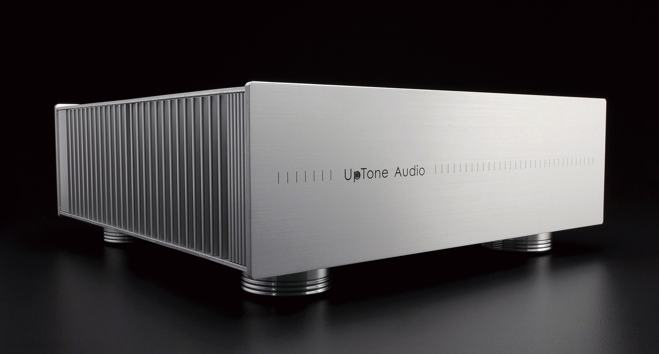
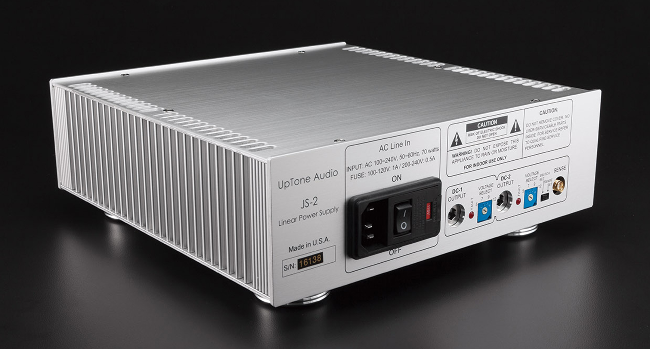
- Many aluminium audio cases and chasis - This Japanese company (Takachi) seems to be a large company dedicated to building these type of enclosures.
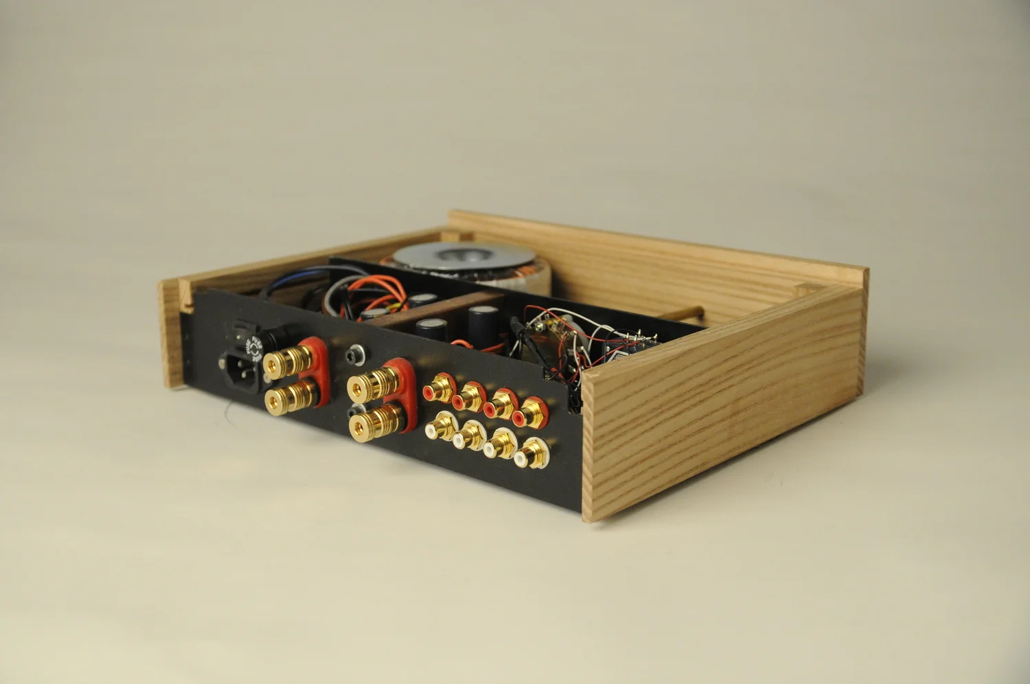
- Amplifier - A beautiful wood Amplifier project with many photos.
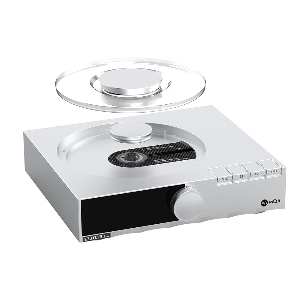 - I love the way this CD loads. I imagine something similar possible using 4 or 5 mm glass and a heavy aluminum or metal weight. For simplicity I would make it square. This design is from the SMSL PL200T CD player.
- Homebuild Hifi - A site with lots of DIY Audio projects. A bit dated but many interesting builds.