Week of the 11/2/2026 - #45
Contents
tech
- Using AI for demo-making
- Computing Sines and Cosines with a Harmonic Oscillator in Size Coding
- New SEGA game releasing soon
art
- The Regular Division of the Plane
Using AI for demo-making

This past weekend the FlashParty demoscene party was held in Ciudad Universitaria. Every year I try to present something at the party, usually an MS-DOS 256-byte intro. This year I was able to create an entry I’m happy with. For the first time, I used AI to help me with the coding process. In these notes I will talk about how I created the entry and how I used AI to improve the code.
First, let’s talk about the effect: parallax scrolling. I’m not sure if this effect is new, but I fell in love with it as implemented in the demo “ReMODed” by 7dump & SandS: https://www.pouet.net/prod.php?which=105924. In that demo there is a beautiful parallax scroll effect with some superimposed animations. Here’s a screenshot from the video:

I knew that I couldn’t reproduce everything that was going on in the demo in 256 bytes, but I thought I could manage the basic parallax effect. So the first step was to understand how it was made. Fortunately, the code for the demo was available, so I downloaded it and started looking at it. The code is a mixture of Pascal and Assembly. It was all in a single file, which made it easier, but it was an elaborate effect: it had some non-trivial palette creation code and it was not easy for me to follow. So this is where I turned to AI for the first time. I basically asked Claude ‘please explain how this code works’, and after a couple of minutes it produced a detailed explanation of all the effects going on in the scene. I asked it to focus specifically on the parallax scroll and ignore everything else (the ‘reflection’ and the animated characters). After a few iterations it had created an .html version of the effect with a very detailed explanation. You can look at it here.
From the very thorough explanation that Claude produced, I understood how I could implement this effect. I would basically set up a camera in the plane, trace a ray, and count which layers the ray crossed. Using 4 bits to represent which layers the ray had crossed, I would compute the color. Here’s a picture of how I would calculate the intersections:
From there I went to ShaderToy to implement this idea. After a day or two I had a ShaderToy version which more or less replicated the effect. Using the same palette that Claude had extracted from the demo’s source code, it looked surprisingly good. Even better, the algorithm was quite simple, so I was pretty sure I would be able to make it work in 256 bytes or less.
void mainImage( out vec4 fragColor, in vec2 fragCoord )
{
    // Normalized pixel coordinates (from 0 to 1)
    vec2 uv = fragCoord/iResolution.xy;

    int x = int(uv.x * 320.) - 160;
    int y = int(uv.y * 240.);
    int idx;
    const vec3 palette[] = vec3[](
     vec3(0., 0., 0.),
     vec3( 0./63., 28./63., 28./63.), // l0
     vec3( 0./63., 42./63., 42./63.), // l1
     vec3( 0./63., 63./63., 63./63.), // l0+l1

     vec3(42./63., 0./63.,   0./63.), // l2
     vec3(32./63., 32./63., 32./63.), // l0+l2
     vec3(40./63., 40./63., 40./63.), // l1+l2
     vec3(45./63., 63./63., 63./63.), // l0+l1+l2

     vec3(28./63., 0./63.,  63./63.), // l3
     vec3(31./63., 31./63., 63./63.), // l0+l3
     vec3(31./63., 39./63., 63./63.), // l1+l3
     vec3(31./63., 63./63., 63./63.), // l0+l1+l3

     vec3(63./63.,  0./63., 31./63.), // l2+l3
     vec3(63./63., 31./63., 63./63.), // l0+l2+l3
     vec3(63./63., 45./63., 63./63.), // l1+l2+l3
     vec3(63./63., 63./63., 63./63.) // l1+l2+l3+l4
    );

    vec3 col;
    int d = 16;
    int bitmap[] = int[](
        0x8e, 0xa6, 0xa0, 0x8a, 0xa4, 0x40,
        0xc8, 0xee, 0xe0, 0xee, 0xc4, 0xe0,
        0xe8, 0xec, 0xa0, 0xee, 0xee, 0xa0
    );

    int x1 = (-2*iFrame % 4096) - 3000;
    int x2 = x;
    int size = 32;
    idx = 0;
    int row = y / size;
    if (row >= 2 && row < 5) {
        for (int i = 0; i < 4; i++) {
            int ofx = x2 - x1;
            if (ofx > 0) {
              ofx /= size;
              int pos = ofx / 8;
              int bit = ofx % 8;
              if (pos < 6 && ((0x80>>bit) & bitmap[6*(row-2)+pos]) != 0) {
                idx += (1 << i);
              }
            }
            x2 += x/8;
        }
    }

    // Output to screen
    fragColor = vec4(palette[idx],1.0);
}
To minimize the size of the data needed for the text, I used the following 3-row font to spell ‘Flash Party’. With this limitation, all the information for the bitmapped text fit in 18 bytes (6 bytes per row). Each byte holds the bitmap pattern for 2 characters. Each character is 4 bits wide (so the font is 4x3).

The bitmap + palette took 18+16=34 bytes in total. I implemented the algorithm in assembly and then had a 201-byte version. It worked but had a lot of issues. As usual, it was based on the memories demo by HellMood. I usually take its bare-bones structure: the timer code and the Rrrola trick to get the x,y coordinates, and then add the code to render the image. It had several problems: the animation wasn’t very smooth and I had to use a lot of cycles in DOSBox to get something decent. There were also a lot of artifacts (bugs) related to how I was doing things. This is when I turned to Claude to help me debug these issues. I have the full conversation with Claude logged in a file in the repo, which you can go through. It really saved me a lot of debugging. One problem I usually have is that debugging this type of code is very time-consuming. I use DEBUG.COM, but it’s very hard to use breakpoints because you need to set the breakpoint but only break after many iterations. Anyway, Claude really helped me fix two or three non-trivial bugs.
Also, to make the demo run better and use less CPU, I realized that I only needed to calculate 3 horizontal lines, since the lines below each one are basically copies. That greatly reduced the CPU usage of the demo, as I would calculate the colors for one line and then copy them to the next 31 lines! This insight was very important to reduce the cost of rendering a frame.
Once I had a smooth, bug-free version, I went on to reduce the size as much as I could so I could fit some music. I reduced it considerably, but at some point I became curious to see how much further the code could be reduced. That’s when I turned to Claude again. I would ask it to generate a new version and tell me how much smaller it could make it, without modifying my code. Once I wasn’t able to reduce it any further, I did eventually peek at its code and used some of its optimizations, basically the ones I understood right away. I left out the things that were not obvious to me. I also learned a couple of valuable lessons about 80x86 assembly that will be useful in the future. Take a look at Appendix I for some of them.
Music
The music in the demo turned out nicely, so I’ll describe how it works in a bit of detail. The main code executes after rendering a frame and is as follows:
  ; Music
  mov si, music
  test bp, 0x07
  jnz skip_play

ch1:
  ; silence ch1 and set fixed volume for ch2
  mov byte [si + 2 + 5], 0      ; ch1
  mov byte [si + 5 + 5], 90     ; ch2

  ; pattern 1
  rol byte [si + 6 + 5], 1
  jc skipmute1

  ; mute ch1
  mov byte [si + 2 + 5], 0

  ; use pattern 1 to gate the synth channel (ch0)
  xor byte [si + 4], 0x7f

skipmute1:
  rol byte [si + 7 + 5], 1
  jc skipmute2

  ; mute ch 2
  mov byte [si + 5 + 5], 0

skipmute2:
  ; switches instruments of ch1 and ch2
  xor byte [si + 1 + 5], 1
  xor byte [si + 4 + 5], 1

playmidi:
  mov dx, 0x330
  mov cl, 6 + 5
  rep  outsb
  inc dx
  outsb

  ; increase volume of ch1
incvol:
  inc [ch1+3]

  ; other code below
  ; ...

music:
  ; synth channel
  db 0xc0  ; change instrument on channel 3
  db 53    ; Instrument: https://en.wikipedia.org/wiki/General_MIDI#Sound_Effects
  db 0x90  ; play note on channel 10
  db 55    ; note number 55
  db 127   ; set volume to 127 but it will be gated

  ; Drum channel
  db 0x99   ; play note on channel 10 (drums)
  db 40
  db 110    ; play with volume = 127
  db 0x99   ; play note on channel 10 (drums)
  db 62
  db 80    ; play with volume = 127

pattern:
  db 0b10011000 ; pattern 1
  db 0b01101100 ; pattern 2
Here’s what’s happening:
- We have 3 “channels” playing: a synth pad (ch0) and two drum channels (ch1 and ch2).
- ch0 uses the “Oohs” MIDI pad (see here).
- ch1 and ch2 toggle instruments on every beat. ch1 switches between a kick and a snare, while ch2 switches between a high and a low conga.
- ch1 starts with volume 0 and fades in by 1 on each frame, which gives the kick and snare some variation.
- Pattern 1 also toggles the volume of the ch0 pad, which gives it some variation.
- Since I had some bytes to spare, I also increase the pitch of the ch0 pad midway through the demo.
Appendix I
Some 80x86 lessons:
- When you have instructions with operands like
[SI]or[DI]and you need to add an offset, you don’t need two instructions:
add si, 100
mov al, [si]
Instead, if the number is a constant, you can do it within the instruction:
mov al, [si + 100]
This is obvious if you are experienced or do a lot of 80x86 coding, but I used it in several places to reduce code size.
- Bit test: at one point in this demo I had to test a bit in memory to determine if it was
0or1. I basically had the offset in bits, so I had to divide by 8 to get the byte offset and take modulo 8 to determine the bit within that byte. I didn’t know aboutBT, which does precisely this in a single instruction! So instead of this:
mov si, fptext
mov cx, ax            ; Save position for later use
shr ax, 3             ; AX / 8 (position / 8)
xchg bx, ax           ; Save byte offset into BX
xor ah, ah            ; Clear AH
mov al, byte [si+bx]  ; Get byte at fptext + offset
and cl, 0x07          ; position % 8
shl al, cl            ; shift out bit
jnc .skip
I could replace it with this (!!!!!):
mov si, ax
bt [si+fptext], ax
jnc .skip
I also had to flip the bits of the text because of where the offset is, but this greatly reduced the size!
-
Short else trick: I just learned this trick from one of Rrřola’s talks. I didn’t use it, but I could have used it many times, so I’ll write it down for my future self. The trick is useful when you have an
if/elsewhere theelseis very short (at most 4 bytes). You basically check for the else condition in the loop and jump to it if the condition is met. If the condition is not met, you execute the long code. At the end of that code you would normally need to jump over the else code. But if it’s short, what you do instead is store the opcode of amovinstruction, which turns those 4 bytes into an immediate value moved into a random/unused register. -
Self-modifying code is slow: Midway through development I tested the code on a 1500 MHz Athlon computer, expecting it to run too fast. That was not the case. I was baffled, so I asked Claude, and there were two main reasons. The first was self-modifying code. Instead of using a register, I would change a byte in the middle of the code on each iteration. It turns out DOSBox doesn’t penalize this, but modifying the code has the unfortunate side effect that the processor has to discard its instruction cache, which makes the code run muuuch slower. Changing this increased the speed considerably, but not as much as I had hoped. The reason was the second lesson:
-
Video RAM is -slow-: The resulting demo only calculates 3 rows and copies the rest from the previous lines by reading from video RAM. This, it turns out, is very slow. The correct way would be to use regular RAM as a buffer to generate the image and then copy it from there to video RAM. Unfortunately, this would probably increase the size of the code, so I couldn’t implement it. I will make a version that uses this method just to test how fast the code can actually run on real hardware.
Links
- Pouet entry - Pouet entry for the ReMODed demo.
- Demozoo entry of Oohs - This is the entry of my demo @Demozoo.
- ShaderToy version - This is the ShaderToy version I made of the main effect.
- Magic of 256-byte x86 intros - Jan ‘Rrřola’ Kadlec - Demobit 2017 - A great talk by Rrřola on size coding.
- Řrřola - Magic of 256-byte x86 intros - part 2. (Demobit 2018) - Another size coding talk by Rrřola.
Computing Sines and Cosines with a Harmonic Oscillator in Size Coding
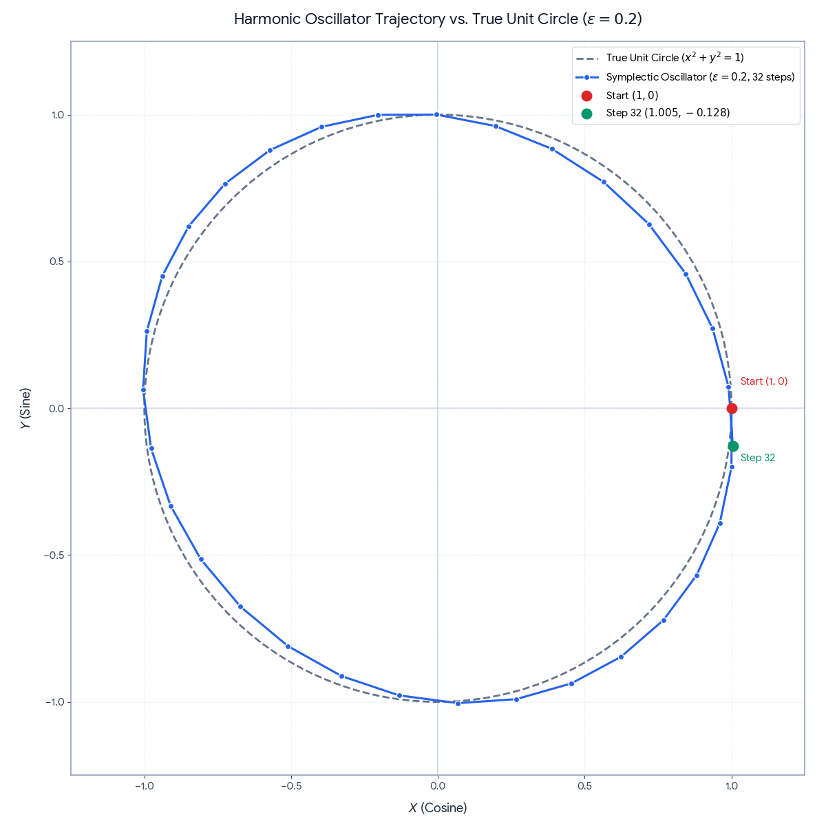
Rrřola mentioned the ‘harmonic oscillator’ trick in one of his talks. I asked Gemini to explain how it works and this is what it came back with. Pretty neat.
To compute sines and cosines in size coding (like 256-byte or 4KB intros), you can use a discrete harmonic oscillator, often called the Minsky circle algorithm or magic circle algorithm. Instead of calling expensive sin() or cos() instructions or storing lookup tables, you generate waves iteratively using just two additions and two multiplications per step.
How the Math Works
A continuous harmonic oscillator is governed by the differential equation:
When discretized using a modified Euler method (specifically, a symplectic Euler integrator), the update equations become:
Notice that the second line uses the newly updated rather than the old . This small change keeps the determinant of the transformation matrix equal to :
Because the determinant is , area (and energy) is preserved, which stops the wave from spiraling outward or decaying to zero.
- Initial state: Set (cosine) and (sine) to start at angle .
- Step size (): Controls the frequency. For small angles, where is the number of steps per full circle. More precisely:
- Phase shift: Because the updates are staggered by half a step, and are slightly off from a true ( radians) phase difference by radians. For small this error is visually unnoticeable.
Size-Coding Implementations
1. C / GLSL (4KB Intros)
In shader or C-based intros, the algorithm reduces to two lines inside a loop. You can often fold the $\epsilon$ multiplication into bit-shifts if you work with fixed-point integers.
// Floating point (e.g., GLSL or C)
float c = 1.0, s = 0.0;
float eps = 0.01; // Frequency step

for (int i = 0; i < 1000; i++) {
    c += eps * s;
    s -= eps * c; // Uses the new 'c'
    // Use 'c' (cos) and 's' (sin) here
}
2. Fixed-Point / Bit-Shift Trick (256-Byte Intros)
In extreme size coding (like x86 assembly), floating-point constants take up precious bytes. If you choose , multiplication becomes a simple arithmetic bit-shift (sar), eliminating the need for any constants or FPU/SSE instructions.
// Integer fixed-point version (no floats, no multiplies)
int c = 1 << 16; // Initial radius = 65536
int s = 0;

for (int i = 0; i < 1000; i++) {
    c += s >> 6; // eps = 1/64 = 2^-6
    s -= c >> 6;
}
3. x86 Assembly (16-bit / 32-bit DOS Intros)
Using 16-bit registers (ax for cosine, bx for sine), the entire sine/cosine generator takes only 8 bytes of machine code:
; Initial setup: AX = 0x4000 (radius), BX = 0
loop_start:
    mov dx, bx      ; Copy sin
    sar dx, 6       ; dx = sin / 64
    add ax, dx      ; cos += sin / 64

    mov dx, ax      ; Copy updated cos
    sar dx, 6       ; dx = cos / 64
    sub bx, dx      ; sin -= cos / 64
    ; Repeat loop
Key Trade-offs & Tips
- Stability vs. Precision: Because the symplectic update preserves area, the trajectory forms a slightly tilted ellipse rather than a perfect circle. As long as , the orbit remains completely stable and will never blow up to infinity, even after millions of iterations.
- Amplitude Scaling: The peak amplitude of (sine) is slightly smaller than (cosine) by a factor of: Keep small (e.g., or bit-shifts of ) so the ellipse looks indistinguishable from a circle.
- No Random Access: Unlike
fsin/fcosor Taylor series approximations, you cannot jump to an arbitrary angle . This method works best for drawing circles, spirals, waveforms, or driving continuous time-based animations.
The Regular Division of the Plane
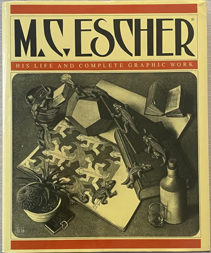
In 1957 the De Roos Foundation, a private press producing limited editions for members only, commissioned Escher to write an essay on his hobby of the regular division of the plane. A year later the essay was published in book form under the title Regelmatige vlakverdeling; it was illustrated with woodcuts that Escher had made especially for it.
Unfortunately, the only copy of this text I know of is included in this book:
I want to do two things:
- Create a physical version of the book. For a long time I’ve wanted to get into bookbinding, and I think printing this book and its illustrations and binding it into a physical copy is a fun project to tackle.
- Create an ebook. This I’ve already done. I scanned my copy of the book and used Claude to run Tesseract 5 locally to get a text version, clean it up, and create a Markdown version, which it later converted to an ebook. I have a private GitHub repository with this. If you want access, ping me (🤫).
Links
- The Regular Division of The Plane at the ‘De Roos’ foundation - An article describing the history of the book.
- Escher Today - This is a fascinating blog which has many articles relating to Escher. Must read for all fans.
New SEGA game releasing soon - Phantom Gear

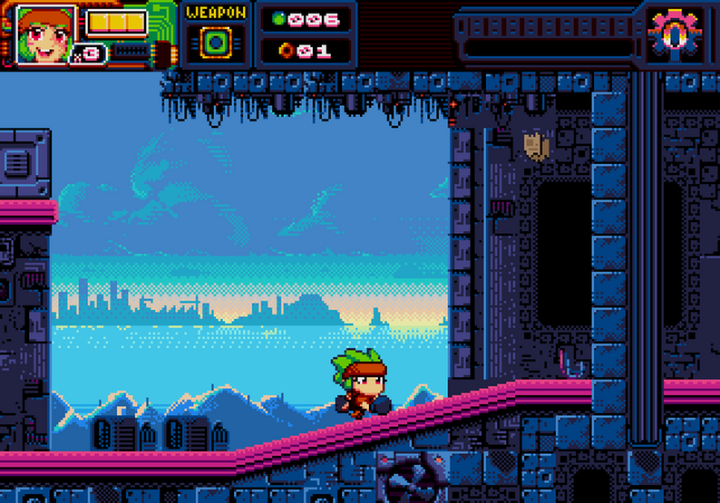
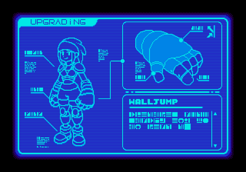
In a few days an Argentinian company will release a new game for the Sega Genesis console in physical format! They have released a demo version on itch.io and it looks very promising.
- Kickstarter campaign - The original campaign that ran in July 2019.