Week of the 03/06/2023 - #10
Contents
tech
- Emulating an Apple II disk with an ESP32/Arduino
art
- Some of my ANSI Art
Emulating an Apple II disk with an ESP32 / Arduino
Last night I did some more research on emulating the Apple ][ disk using an ESP32 or Arduino. Basically there was a message in the FujiNetWIFI Discord server saying that it now supports Apple II disks! I looked at the code and they are using a feature of the ESP32 that allows you to modulate a carrier with a pulse sequence of bits. It’s very precise and simple to use. It’s a great idea! The only reason I’m not sure is that the ESP32 runs on 3.3V and I’m reluctant to connect it to my Apple //c which runs a standard TTL 5V. I suspect it should work fine but … don’t want to kill it. I re-read some of the code for the Arduino and I belive it’s not too complicated to write precise code with the correct timing by cycle counting.
I belive I can tweak the SendPacket function call in this code from packet_16mhz.S (to send the track data to the disk):
//*****************************************************************************
//
// Apple //c Smartport Compact Flash adapter
// Written by Robert Justice  email: rjustice(at)internode.on.net
//
// Assembler routines for sending and receiving the smartport packets
// These are timing sensitive and assume a clk frequency of 16Mhz
//
//*****************************************************************************

// required for register definitions
#include <avr/io.h>

//*****************************************************************************
// Function: SendPacket
// Parameters: packet_buffer pointer
// Returns: status (not used yet, always returns 0)
//
// Description: This handles the ACK and REQ lines and sends the packet from the
// pointer passed to it. (packet_buffer)
//
//*****************************************************************************
.global SendPacket

SendPacket:
          mov  XL,r24                 ;mov buffer pointer into X
          mov  XH,r25

          sbi  _SFR_IO_ADDR(PORTC),5  ;set ACK high to signal we are ready to send
          ;ldi  r24,'A'               ;for debug, A indicates ACK is high
          ;call uart_putc             ;output to serial port

1:        sbic _SFR_IO_ADDR(PIND),2   ;wait for req line to go high
          rjmp contin                 ;this indicates host is ready to receive packet
          ;ldi  r24,'r'               ;for debug, r indicates REQ is low
          ;call uart_putc             ;output to serial port
          rjmp 1b

contin:   ;ldi  r24,'R'               ;for debug, R indicates REQ is high
          ;call uart_putc             ;output to serial port
;
;                                     ;Totals for loops             ;
;
nxtsbyte: ld   r23,x+                 ;59        ;43         ;2   get first byte from buffer
          cpi  r23,0                  ;60        ;44         ;1   zero marks end of data
          breq endspkt                ;61        ;45         ;1/2

          ldi  r25,8                  ;62        ;46         ;1   8bits to read
                                                 ;Clr  ;Set
nxtsbit:  sbrs r23,7                  ;64(Set) ;64      ;47   ;48   ;1/2 send bit 7 first
                                      ;63(Clr)
          rjmp sbitclr                ;64+1             ;48+1       ;2   bit is clear
          sbi  _SFR_IO_ADDR(PORTD),6                          ;2    ;2   set bit for 1us (14 cycles)-->16 cycles for 16Mhz(2 more)

          ldi  r24,4                                                ;1   |delay total of 12 cycles
3:        dec  r24                                                  ;1   | each loop +3 final loop +2
          brne 3b                                                   ;1/2 | 1 + 3x3 + 1x2 = 11
                                                              ;14
          nop                                                 ;15   ;1
          nop                                             ;16   ;1

          cbi  _SFR_IO_ADDR(PORTD),6                          ;2    ;2   clr bit for 3us (42 cycles)-->48 cycles for 16Mhz(6 more)
                                                                    ;                                            2 more loops
          dec  r25                                            ;3    ;1   dec bit counter
          breq nxtsbyt1                                       ;4    ;1/2
          rol  r23                                            ;5    ;1

          ldi  r24,13                                               ;1   |delay total of 39 cycles
3:        dec  r24                                                  ;1   |  each loop +3 final loop +2
          brne 3b                                                   ;1/2 |  1 + 12x3 + 1x2 = 39
                                                              ;44

          rjmp nxtsbit                                        ;46   ;2

nxtsbyt1:                                               ;5          ;    delay to makeup 3us (42 cycles total)-->48 cycles for 16Mhz(6 more)
                                                                    ;                                            2 more loops
          ldi  r24,11                                               ;1   |delay total of 33 cycles
3:        dec  r24                                                  ;1   | each loop +3 final loop +2
          brne 3b                                                   ;1/2 | 1 + 10x3 + 1x2 = 33
                                                    ;38
          nop                                           ;39         ;1

          rjmp nxtsbyte                                 ;41         ;2

; bit is clr, we need to check if its the last one, otherwise delay for 4us before next bit
sbitclr:  dec  r25                             ;2                   ;1
          breq nxtsbycl               ;4       ;3                   ;1/2 end of byte, delay then get nxt
          rol  r23                             ;4                   ;1
                                                                    ;    delay to makeup 4us (56 cycles total)-->64 cycles for 16Mhz(8 more)
                                  ;                                            2 more loops +2 nops
          ldi  r24,18                                               ;1   |delay total of 54 cycles
3:        dec  r24                                                  ;1   | each loop +3 final loop +2
          brne 3b                                                   ;1/2 | 1 + 17x3 + 1x2 = 54
                                               ;58
          nop                                  ;59                  ;1
          nop                                  ;60                ;1
          rjmp nxtsbit                         ;62                  ;2

nxtsbycl:                                                           ;    delay to makeup 4us (56 cycles total)-->64 cycles for 16Mhz(8 more)
                                  ;                                            2 more loops +2 nops
                                                                    ;
          ldi  r24,16                                               ;1   |delay total of 48 cycles
3:        dec  r24                                                  ;1   | each loop +3 final loop +2
          brne 3b                                                   ;1/2 | 1 + 15x3 + 1x2 = 48
                                      ;52
          nop                         ;53                           ;1
          nop                         ;54                           ;1
          nop                         ;55                           ;1

          rjmp nxtsbyte               ;57                           ;2


endspkt:  cbi  _SFR_IO_ADDR(PORTC),5  ;set ACK(BSY) low to signal we have sent the pkt
          ;ldi  r24,'a'                ;for debug, a indicates ACK is low
          ;call uart_putc              ;output to serial port

1:        ldi  r24,5
          sbis _SFR_IO_ADDR(PIND),2   ;wait for REQ line to go low
          rjmp finishs                ;this indicates host has acknowledged ACK
          dec  r24
          brne 1b
          rjmp error

finishs:  ;ldi  r24,'r'                ;for debug, r indicates REQ is low
          ;call uart_putc              ;output to serial port
          clr  r25
          clr  r24                    ;return no error
          ret

error:    clr  r25
          ldi  r24,1
          ret
While reading about timing I came across a couple of projects that allow you to generate VGA from an Arduino that talk a little about timing.
Links
- FujiNetWIFI source code
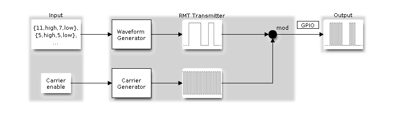
- Remote control module driver documentation - The ESP32 has a module driver that can be used to modulate a carrier signal with a waveform. The FujiNetWIFI source code seems to use this functionality to generate the bitstream that is read from the disk and send it to the IWM controller.
- WOZ Disk Image Reference 2.1 - This is the specification for revision 2.1 of the WOZ image format. In it you can understand a little more how the information is stored on the disk and what is transmitted to the IWM. Here is the relevant part for us:
“On the Apple II, floppy disk data is written to the disk based on a 4µs clock. Whenever there is a 1 bit to write, the polarity of the magnetic flux under the drive head is transitioned from its current state to the opposite. If a zero needs to be written out, the 4µs clock is skipped (no transition occurs).
The MC3470 chip is the heart of the Apple II floppy drive. It reads the magnetic flux pattern off the disk and sends out a pulse for every flux transition it sees. This gives us back our 1 bits and our 0 bits come from the 4µs clock going by with no pulse.
One of the nice features of the MC3470 is that it has an internal amplification system to adapt to the varying magnetic strengths of each disk. If it has a hard time reading the disk, it can turn up its amp until it finds the signal. It allows the drive to read a wide assortment of disks. The Apple II uses GCR encoding to store bits on the disk. It is a very efficient system that was used widely on many platforms, because it doesn’t use clock bits to frame up your data bits, giving you more room to write data. This technique also has a drawback though, which is never being able to record more than two 0 bits in a row. It is why data on an Apple II is stored as nibbles instead of plain binary bytes.”
- fddEMU - An AVR (atmega328p) based floppy drive emulator for PC
- Arduino Uno output to VGA monitor - This post shows how you can output VGA signals to a monitor, turning your Uno (or similar) processor into a “video card”. In this code the writer is using USART in SPI mode (MSPIM). This has the disadvantage of adding a start and end bit which we can’t control.
/*
 VGA video generation

 Author:   Nick Gammon
 Date:     20th April 2012
 Version:  1.2

 Version 1.0: initial release
 Version 1.1: code cleanups
 Version 1.2: more cleanups, added clear screen (0x0C), added scrolling


 Connections:

 D1 : Pixel output (470 ohms in series to each one of R, G, B)   --> Pins 1, 2, 3 on DB15 socket
 D3 : Horizontal Sync (68 ohms in series) --> Pin 13 on DB15 socket
 D10 : Vertical Sync (68 ohms in series) --> Pin 14 on DB15 socket

 Gnd : --> Pins 5, 6, 7, 8, 10 on DB15 socket

 PERMISSION TO DISTRIBUTE

 Permission is hereby granted, free of charge, to any person obtaining a copy of this software
 and associated documentation files (the "Software"), to deal in the Software without restriction,
 including without limitation the rights to use, copy, modify, merge, publish, distribute, sublicense,
 and/or sell copies of the Software, and to permit persons to whom the Software is furnished to do so,
 subject to the following conditions:

 The above copyright notice and this permission notice shall be included in
 all copies or substantial portions of the Software.


 LIMITATION OF LIABILITY

 The software is provided "as is", without warranty of any kind, express or implied,
 including but not limited to the warranties of merchantability, fitness for a particular
 purpose and noninfringement. In no event shall the authors or copyright holders be liable
 for any claim, damages or other liability, whether in an action of contract,
 tort or otherwise, arising from, out of or in connection with the software
 or the use or other dealings in the software.

*/

#include <TimerHelpers.h>
#include <avr/pgmspace.h>
#include "screenFont.h"
#include <avr/sleep.h>
#include <Wire.h>

#define BETA_ARDUINO ARDUINO < 100

const byte pixelPin = 1;     // <------- Pixel data
const byte hSyncPin = 3;     // <------- HSYNC
const byte MSPIM_SCK = 4;    // <-- we aren't using it directly
const byte vSyncPin = 10;    // <------- VSYNC

const int horizontalBytes = 20;  // 160 pixels wide
const int verticalPixels = 480;  // 480 pixels high

const byte i2cAddress = 42;

// Timer 1 - Vertical sync

// output    OC1B   pin 16  (D10) <------- VSYNC

//   Period: 16.64 ms (60 Hz)
//      1/60 * 1e6 = 16666.66 µs
//   Pulse for 64 µs  (2 x HSync width of 32 µs)
//    Sync pulse: 2 lines
//    Back porch: 33 lines
//    Active video: 480 lines
//    Front porch: 10 lines
//       Total: 525 lines

// Timer 2 - Horizontal sync

// output    OC2B   pin 5  (D3)   <------- HSYNC

//   Period: 32 µs (31.25 kHz)
//      (1/60) / 525 * 1e6 = 31.74 µs
//   Pulse for 4 µs (96 times 39.68 ns)
//    Sync pulse: 96 pixels
//    Back porch: 48 pixels
//    Active video: 640 pixels
//    Front porch: 16 pixels
//       Total: 800 pixels

// Pixel time =  ((1/60) / 525 * 1e9) / 800 = 39.68  ns
//  frequency =  1 / (((1/60) / 525 * 1e6) / 800) = 25.2 MHz

// However in practice, it is the SPI speed, namely a period of 125 ns
//     (that is 2 x system clock speed)
//   giving an 8 MHz pixel frequency. Thus the characters are about 3 times too wide.
// Thus we fit 160 of "our" pixels on the screen in what usually takes 3 x 160 = 480

const byte screenFontHeight = 8;
const byte screenFontWidth = 8;

const int verticalLines = verticalPixels / screenFontHeight / 2;  // double-height characters
const int horizontalPixels = horizontalBytes * screenFontWidth;

const byte verticalBackPorchLines = 35;  // includes sync pulse?
const int verticalFrontPorchLines = 525 - verticalBackPorchLines;

volatile int vLine;
volatile int messageLine;
volatile byte backPorchLinesToGo;

enum SEND_COMMANDS { CLRSCR = 1, CLREOL, GOTOXY, ESC = 27 };
enum STATES { NORMAL, GOT_ESCAPE, GOT_GOTOXY, GOT_X };

char message [verticalLines]  [horizontalBytes];
byte column, line;
STATES state = NORMAL;
byte x, y;  // for gotoxy


// ISR: Vsync pulse
ISR (TIMER1_OVF_vect)
  {
  vLine = 0;
  messageLine = 0;
  backPorchLinesToGo = verticalBackPorchLines;
  } // end of TIMER1_OVF_vect

// ISR: Hsync pulse ... this interrupt merely wakes us up
ISR (TIMER2_OVF_vect)
  {
  } // end of TIMER2_OVF_vect

// called by interrupt service routine when incoming data arrives

/*
Expected formats are:
   * ordinary text:           gets displayed
   * carriage-return (0x0D):  returns cursor to start of current line
   * newline (0x0A):          drops down a line and also goes to the start of the line
   * clear screen (0x0C):     clear screen, return cursor to 1,1
   * ESC (0x1B) followed by:
      * 1 : clear screen, return cursor to 1,1
      * 2 : clear to end of current line
      * 3 : go to x,y ... next two bytes are X and then Y: one-relative

  All writing wraps, eg. text wraps at end of line, then end of screen back to line 1, column 1.
  A gotoxy out of range is ignored.
*/

void receiveEvent (int howMany)
 {
  while (Wire.available () > 0)
  {
    byte c;
#if BETA_ARDUINO
    c = Wire.receive ();
#else
    c = Wire.read ();
#endif

    // first check state ... see if we are expecting a command or an x/y position
    switch (state)
      {
      // normal is, well, normal unless we get an ESC character
      case NORMAL:
          switch (c)
            {
            case ESC:
              state = GOT_ESCAPE;
              break;

            // otherwise just display the character
            default:
               message [line] [column] = c;
               if (++column >= horizontalBytes)
                 {
                 column = 0;
                 line++;
                 } // end wrapped line

              if (line < verticalLines)
                  break;
            // if wrapped past end of buffer, fall through to do a newline which will scroll up

            // newline starts a new line, and drops down to do a carriage-return as well
            case '\n':
              // end end? scroll
              if (++line >= verticalLines)
                {
                // move line 2 to line 1 and so on ...
                memmove (& message [0] [0], & message [1] [0], sizeof message - horizontalBytes);
                // clear last line
                memset (&message [verticalLines - 1] [0], ' ', horizontalBytes);
                // put cursor on last line
                line = verticalLines - 1;    // back to last line
                }
            // fall through ...

            // carriage-return returns to start of line
            case '\r':
              column = 0;
              break;

            // clear screen
            case '\f':
              memset (message, ' ', sizeof message);
              line = column = 0;
              break;

             }  // end of switch on incoming character

          break;  // end of NORMAL

        // got ESC previously
        case GOT_ESCAPE:
          switch (c)
            {
            // clear screen ... just do it
            case CLRSCR:
              memset (message, ' ', sizeof message);
              line = column = 0;
              state = NORMAL;
              break;

            // clear to end of line
            case CLREOL:
              memset (&message [line] [column], ' ', horizontalBytes - column);
              state = NORMAL;
              break;

            // gotoxy expects two more bytes (x and y)
            case GOTOXY:
              state = GOT_GOTOXY;
              break;

            // unexpected ... not recognized command
            default:
              state = NORMAL;
              break;
            } // end of switch on command type
          break;  // end of GOT_ESCAPE

        // we got x, now we want y
        case GOT_GOTOXY:
          x = c - 1;  // make zero-relative
          state = GOT_X;
          break;

        // we now have x and y, we can move the cursor
        case GOT_X:
          y = c - 1;  // make zero-relative

          // if possible that is
          if (x < horizontalBytes && y < verticalLines)
            {
            column = x;
            line = y;
            }
          state = NORMAL;
          break;

        // unexpected ... not recognized state
        default:
          state = NORMAL;
          break;
      } // end of switch on state

  }  // end of while available
}  // end of receiveEvent

void setup()
  {

  // initial message ... change to suit
  for (int i = 0; i < verticalLines; i++)
    sprintf (message [i], "Line %03i - hello!", i);

  // disable Timer 0
  TIMSK0 = 0;  // no interrupts on Timer 0
  OCR0A = 0;   // and turn it off
  OCR0B = 0;

  // Timer 1 - vertical sync pulses
  pinMode (vSyncPin, OUTPUT);
  Timer1::setMode (15, Timer1::PRESCALE_1024, Timer1::CLEAR_B_ON_COMPARE);
  OCR1A = 259;  // 16666 / 64 µs = 260 (less one)
  OCR1B = 0;    // 64 / 64 µs = 1 (less one)
  TIFR1 = bit (TOV1);   // clear overflow flag
  TIMSK1 = bit (TOIE1);  // interrupt on overflow on timer 1

  // Timer 2 - horizontal sync pulses
  pinMode (hSyncPin, OUTPUT);
  Timer2::setMode (7, Timer2::PRESCALE_8, Timer2::CLEAR_B_ON_COMPARE);
  OCR2A = 63;   // 32 / 0.5 µs = 64 (less one)
  OCR2B = 7;    // 4 / 0.5 µs = 8 (less one)
  TIFR2 = bit (TOV2);   // clear overflow flag
  TIMSK2 = bit (TOIE2);  // interrupt on overflow on timer 2

  // Set up USART in SPI mode (MSPIM)

  // baud rate must be zero before enabling the transmitter
  UBBR0 = 0;  // USART Baud Rate Register
  pinMode (MSPIM_SCK, OUTPUT);   // set XCK pin as output to enable master mode
  UCSR0B = 0;
  UCSR0C = bit (UMSEL00) | bit (UMSEL01) | bit (UCPHA0) | bit (UCPOL0);  // Master SPI mode

  // prepare to sleep between horizontal sync pulses
  set_sleep_mode (SLEEP_MODE_IDLE);

  // for incoming data to display from I2C
  Wire.begin (i2cAddress);
  Wire.onReceive (receiveEvent);

}  // end of setup

// draw a single scan line
void doOneScanLine ()
  {

  // after vsync we do the back porch
  if (backPorchLinesToGo)
    {
    backPorchLinesToGo--;
    return;
    }  // end still doing back porch

  // if all lines done, do the front porch
  if (vLine >= verticalPixels)
    return;

  // pre-load pointer for speed
  const register byte * linePtr = &screen_font [ (vLine >> 1) & 0x07 ] [0];
  register char * messagePtr =  & (message [messageLine] [0] );

  // how many pixels to send
  register byte i = horizontalBytes;

  // turn transmitter on
  UCSR0B = bit (TXEN0);  // transmit enable (starts transmitting white)

  // blit pixel data to screen
  while (i--)
    UDR0 = pgm_read_byte (linePtr + (* messagePtr++));

  // wait till done
  while (!(UCSR0A & bit(TXC0)))
    {}

  // disable transmit
  UCSR0B = 0;   // drop back to black

  // finished this line
  vLine++;

  // every 16 pixels it is time to move to a new line in our text
  //  (because we double up the characters vertically)
  if ((vLine & 0xF) == 0)
    messageLine++;

  }  // end of doOneScanLine

void loop()
  {
  // sleep to ensure we start up in a predictable way
  sleep_mode ();
  doOneScanLine ();
 }  // end of loop
On that same thread there is another way to do it: basically blit all DATA using the PORTD register. The timing is pretty simple. From the post:
The code to output the pixels is a simple loop:
while (i--
    PORTD = * messagePtr++;
It relies on the pixel data pins all being on the same hardware port (PORTD in this case).
The generated assembler code is:
  while (i--)
    PORTD = * messagePtr++;
(2) 194:	89 91       	ld	r24, Y+
(1) 196:	8b b9       	out	0x0b, r24	; 11
(1) 198:	91 50       	subi	r25, 0x01	; 1
(2) 19a:	e0 f7       	brcc	.-8      	; 0x194

-------
6 cycles in loop = 375 nS
Thus it takes 6 cycles (375 nS) per pixel, and the 60 pixels will take 22.5 uS which is inside the 25.4 uS allowed time for the visible frame.
By adding NOP instructions I think I can use this to output 1bit (4uS) rather simply.
- packet_16mhz.S - This code shows how you can transfer information and has some ASM examples.
- VGAX Library for Arduino UNO and MEGA - This is a VGA library for Arduino UNO and Arduino MEGA.
- Sandro Maffiodo - Author of the previous library and has some nice projects
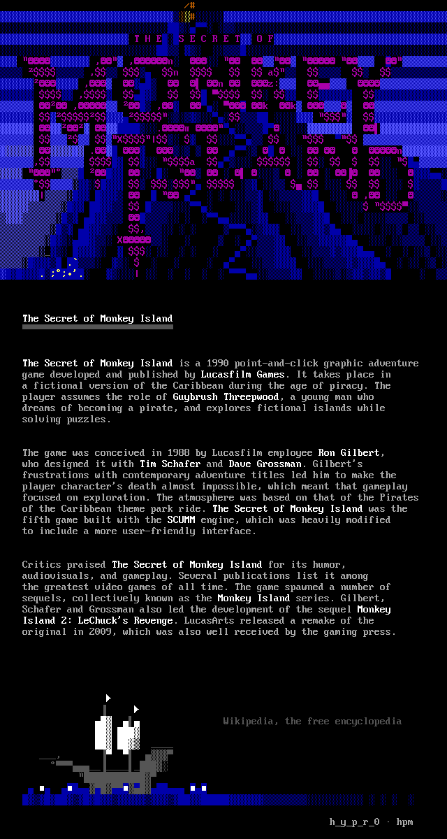
Some of my ANSI Art
Here are some of my ANSI art images. The Monkey Island pieces were drawn for the HPM release 2022 / hpm-002.


This is a piece I did by taking a screenshot of the movie, posterizing it in Gimp and then reproding it in ANSI.
Final piece: Morpheus and Neo finally meet. 160x40 in 8x8 VGA font.

Posterized version of the screenshot taken from the movie.

Original shot from the movie.