Week of the 06/17/2024 - #25
Contents
tech
- Apple //c Arduino drive - Success!
- Apple //c spare parts and resources
- How to wire and use an ATMega328p microcontroller
- Other Apple //c related projects & articles
art
- Messing around with Orca and a Yamaha DX21
Apple //c Arduino drive - part 4
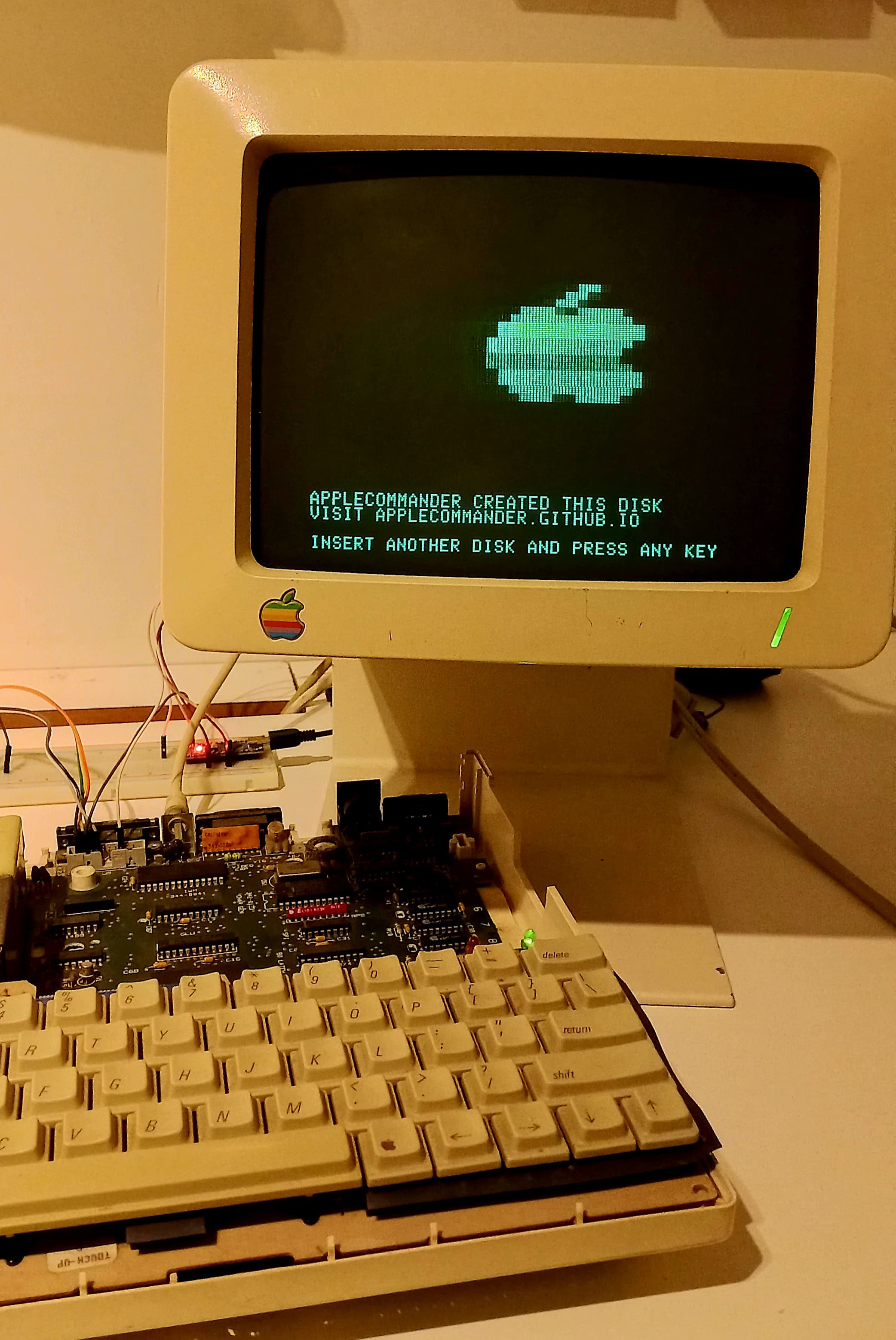
This weekend I finally managed to read sector 0 of track 0 and load the first part of the OS on my Apple //c hardware! It took a lot of reading but I learned a lot of the details of how the Apple II hardware stores information on a 5 1/4” disk. Here are my notes:
- I started looking into the Arduino Nano processor datasheet to see if there was a way to send serial data easily without having to loop through it and send it, bit by bit on a pin.
- I looked at SPI which seemed promosing but after implementing it and getting it to work I realized that SPI work on a byte level and basically adds extra time between bytes really ruining the timing of the bits. I spent a couple of days until I realized it wasn’t going to work. At least I learned a bit how SPI works.
- Finally I went back to the exising code used in the SmartportSD project. Basically took out their
SendPacketroutine and used that code to send the stream of bytes to the drive. - Looking at the signals with the signal analyzer I talked about a couple of weeks ago the timing is very good. It’s not 100% exact. When you look at 50 bytes you get a little less than a microsecond accumlated error. It turns out it’s not a problem.
- I used the
dks2woz.cprogram to take an Applecommander DOS disk and covert it into a.wozfile. - Using the wozardry python library I created a simple Python3 script which takes the
.wozimage and extracts the bit information of the track and dumps it to a C header file. - With the 3 files: the
inothat usesstreamData()function and the disk header with the information I hooked it up to my Apple //c. - An additional problem I came accross was that the Arduino has only 2KB of SRAM memory and a single track has around 6KB! To sort this out I had to put the track data in PROGMEM in the Arduino, chop it into 512KB blocks and send the data to the Apple. Eventually this worked because we are only interested in getting it to read track 0 sector 0 but in the long run I’m going to need to separate sector data because when the IWM is reading the track information it can’t handle breaks which happen when we need to read the following 512KB from the track data array. I use
memcpy_P()function call which is fast but it takes more than 300 microseconds to copy this information which will break things. My guess is that I’ll need look at the track data and separate it into sectors and send one sector at a time.

- Of course it did not work initially.
- To debug the boot sequence this was really handy: C600 ROM disassembly. The code has a lot more comments than the listing found in Apple //c Reference Manual.
- To debug it what I would do is copy the
$C600code into$A00and add0x00in different places from the monitor to break at different times and look what was going on. Like this:
] CALL -151
* A00<C600.C6FFM
* A5EL

LDA $C08C,X
BPL $A5E
EOR #$D5
BNE $A57
LDA $C08C,X
BPL $A67
CMP #$AA
BNE $A63
NOP
LDA $C08C,X
BPL $A67
CMP #$96
....
The previous sequence for example looks for 0xD5 0xAA 0X96 to read the sector header. By breaking after the last compare I can see if it was finding the header. This worked from the first time. Next I looked at the data that it was reading from the drive. To do this the key routines are $C6A6 ($AA6) which reads the 86 bytes with the ‘2’ part of the 6-and-2 encoding. This data is saved at address $300. The other key piece is $C6BA ($ABA) which reads the remaingin 256 bytes and stores them in $800. To look at the data exactly as it was being pulled from the drive you need to modify the code to note ‘decode’ it. For example instead of this code:
LDY #$56
STY $3C
LDY $C08C,X
BPL $AAA
EOR $2D6,Y
LDY $3C
STA ($26),Y
INY
BNE $ABA
I would replace EOR $2D6,Y with a TYA instruction to put the byte just read from the drive and copy it to the A accumulator and two NOP instructions. This way after running this code I could see the data read from the drive in the range $300 - $356 with:
* 300.360
Inspecting this data and comparing with the woz file it was exactly the same content. This was great! At least it was reading the first 80 or 90 bytes perfectly. With the same technique I looked at the data in $800. It looked exactly the same except for the laste 20 or 30 bytes which where completly off! Instead of having 0x96 0x96 0x96 ... I would see secuences of same numbers but not 0x96. Initially I thought the problem was that small offset in the timing which might be accumulating. I went back to the Arduino IDE and created a long stream of 0x80 pulses and measured the distance between them. Looking into this I noticed that in most places it was precisely 32 microseconds but once in a while it would be several microseconds longer. So that meant that it wasn’t a cummulative effect. It was something else. Looking again at the SmartportSD project I noticed there were several calls to a noInterrupts() method! That was it! What seem to be happening was that every once in a while there would be an interrupt in the ATmega328 which would ruin the timing. Once I added this code to suspend all interrupts while sending the data everything worked and I got to finally read a complete 256 byte sector from the Arduino.
Here’s the source for the Arduino code:
#include <SPI.h>
// Track0 data
#include "track-full.h"
// Size of our buffer to transfer data to Apple //c.
#define BUFFER_SIZE 512
//
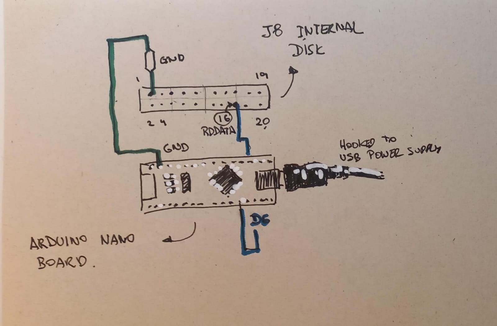
// To connect this to the Apple //c you need to connect:
//
// - pin 1 of the INTERNAL DISK J8 connector to the GND
// pin of the Arduino Nano
// - pin 16 (RDDATA) of the INTERNAL DISK J8 connector
// to pin D6 of the Arduino Nano
//
// Connect the Arduino to a USB to power it up and let
// the turn on the Apple //c.
//
#define CHIPSELECT 2 // pin 2 (D2 on the board or PD2)
#define DATABUS 6 // RDDATA of the INTERNAL DISK J8
// to (D6 on the board or PORTD bit 6).
// Declaration of code which sends data to the Drive
extern "C" unsigned char StreamData(unsigned char*);
void setup() {
pinMode(CHIPSELECT, OUTPUT);
pinMode(DATABUS, OUTPUT);
digitalWrite(CHIPSELECT, HIGH);
}
void loop() {
unsigned char track_buffer[BUFFER_SIZE + 1];
unsigned int block_num;
PORTD &= ~(_BV(6)); // set DATABUS low
// We asume TRACK_LENGTH / BUFFER_SIZE is an integer.
unsigned num_blocks = TRACK_LENGTH / BUFFER_SIZE;
for(block_num = 0; block_num < num_blocks; block_num++) {
memcpy_P(
track_buffer,
&track_data[block_num * BUFFER_SIZE],
BUFFER_SIZE
);
track_buffer[BUFFER_SIZE] = 0x00;
digitalWrite(CHIPSELECT, LOW);
noInterrupts();
StreamData((unsigned char*) track_buffer);
interrupts();
digitalWrite(CHIPSELECT, HIGH);
}
}
the stream_data.S code:
#include <avr/io.h>

//*************************************************************
// Function: StreamData
// Parameters: packet_buffer pointer
// Returns: always returns 0
//
// Description: This will stream the data in X until a 0x00
// is found which indicates end of data. As input you get the
// packet_buffer address in r24 and r25. The output is sent to
// pin 6 of PORTD.
//
// This code is taken from:
//
// https://gitlab.com/nyankat/smartportsd/ file packet_16mhz.S
//
// I've removed the cycle count on each line but this code
// is cycle counted so you should not add a single NOP
// instruction which would screw all the timing. The code
// generates a 1us pulse and 3us delay (for a 1) and a 4us
// delay for a 0. It works perfectly with a 16Mhz Arduino Nano.
//
//*************************************************************
.global StreamData

StreamData:

          mov  XL,r24   ; mov buffer pointer into X
          mov  XH,r25

          // set transmit bit low
          cbi  (_SFR_IO_ADDR(PORTD)),6

          // same code as in SendPacket of SmartportSD project
          // ...
          // ...

enddata:
          clr  r25
          clr  r24                    ;return no error
          ret
and finally the track data:
#define TRACK_LENGTH        6656

const PROGMEM unsigned char track_data[] = {
  0xff, 0x3f, 0xcf, 0xf3, 0xfc, 0xff, 0x3f, 0xcf,
  0xf3, 0xfc, 0xff, 0x3f, 0xcf, 0xf3, 0xfc, 0xff,
  0x3f, 0xcf, 0xf3, 0xfc, 0xff, 0x3f, 0xcf, 0xf3,
  0xfc, 0xff, 0x3f, 0xcf, 0xf3, 0xfc, 0xff, 0x3f,
  0xcf, 0xf3, 0xfc, 0xff, 0x3f, 0xcf, 0xf3, 0xfc,
  ...
  0xd5, 0xaa, 0x96, 0xff, 0xfe, 0xaa, 0xaa, 0xaa,
  0xaa, 0xff, 0xfe, 0xde, 0xaa, 0xeb, 0xff, 0x3f,
  0xcf, 0xf3, 0xfc, 0xff, 0x3f, 0xcf, 0xf3, 0x56,
  0xaa, 0xb7, 0xaf, 0xae, 0x5a, 0xce, 0x9b, 0xaa,
  0xf3, 0xb6, 0xb3, 0xa6, 0xe6, 0xb7, 0x37, 0xdb,
  0xb7, 0x37, 0x37, 0x7e, 0xcf, 0x67, 0x7a, 0x5a,
  0x9f, 0x9a, 0xd6, 0x5a, 0xd2, 0x76, 0x7b, 0xb6,
  0xd3, 0x9b, 0xee, 0xbf, 0x96, 0xf7, 0xa6, 0x77,
  ...
};
Links
- WriteToWoz and GenWoz - These two projects by the Fr3nchT0uch demo group allow you to create a blank WOZ file and then populate tracks/sectors with whatever binary content you want.
- DirectWrite - Another Fr3nchT0uch project to write binary data directly to
dskimages. - Kessessay - A small tool that shows some basic hardware specs of your Apple II.
- Prodos 8 - A PRODOS version for the Apple II. From the site:
- The last official release of ProDOS was 2.0.3 in 1993.
- On September 15th, 2016 John Brooks released the 2.4 version of ProDOS on the 30th anniversary of the introduction of the Apple IIgs.
- Originally ProDOS did not include support for the original Apple ][ or the ][+, however This release added support for the Apple ][ and ][+ models, making it the first release of ProDOS that would run on ALL Apple II’s.
- The release includes Bitsy Bye, a menu-driven program launcher that allows for navigation through files on multiple floppy drives
- DSK file format :
.dskis just about the simplest format there is: all 35 tracks of a 16 sector disk, with the sectors in order 0-15. Every .dsk file is 143,360 bytes long because it’s 256 * 16 * 35 bytes. For PRODOS disks the order of the sectors is different. - Applecommander disk utiliy - Allows you to manipulate DOS / PRODOS dsk images. Main page
Messing around with Orca and a Yamaha DX21
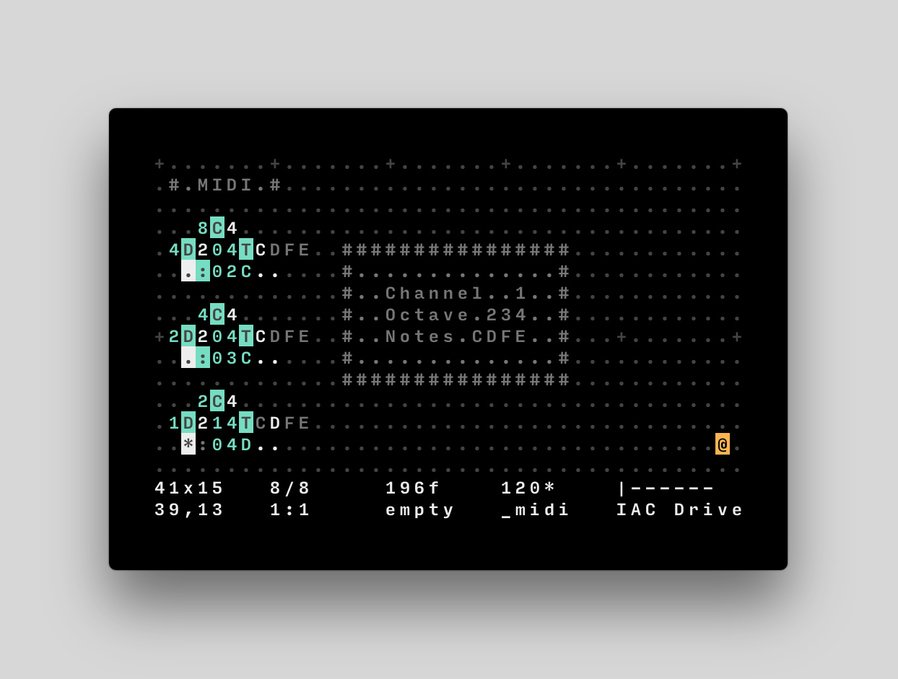
Today I connected a Yamaha DX21 keyboard to my laptop via MIDI and trigger it using Orca. Here are a couple of notes from this experience:
- There are several links to the project: wiki.xxivv.com / 100r.co / itch.io.
- The DX21 can be configured in SPLIT mode which basically splits the keyboard into two regions. You can then map two instruments to these two regions. This way you can have a bass (my favorite is the Solid Bass instrument and another instrument (Celeste is nice) for the other part.
- With Orca you can create different rhythms. This sounds nice for the bass and has a slightly off beat sound:
  .D2
   :04A1..
  .D3
   :04C1..
- Found a couple of good YouTube videos with tutorilas: Learn ORCΛ Livecoding ~ IN DEPTH TUTORIAL (Pt. 1) / Learn ORCΛ Livecoding ~ IN DEPTH TUTORIAL (Pt.2) / ORCA Sequencer Intro (Experimental Livecoding!)
- The part 2 of the Orca YT tutorial shows a way to build a simple 4 track tracker using Orca. This is in a nutshell how it works:
   ····Cg·············
   ·D1·435Q····#·····#
   ·*;abcde····#·····#
   ············#·····#
   ············#abcde#
   ············#·····#
   ············#·····#
   ············#·····#
   ············#·····#
   ············#·····#
   ············#·····#
   ············#·····#
   ············#·····#
   ············#·····#
   ············#·····#
   ············#·····#
- I used the version in this source hut repo which compiled without too much effort in Linux.
- Downloaded this Orca cheatsheet PDF.
Apple //c spare parts and resources
While looking for other Apple II related stuff I came across several interesting resources:
- What’s keeping this Apple IIc from working? - a thorough and in-depth video on debugging hardware issues with Apple //c.
- Repairing Apple IIc RAM (Also The Stuff I Broke) - Another video on replacing Apple //c RAM chips.
- Socket IC 16 Pin Machine Tooled Low Profile 0.3 Inch Wide - Low profile IC sockets which you can use to replace the RAM chips on an Apple //c so that if the RAM chip dies or doesn’t work you don’t need to resolder it. Since the 5 1/4” drive sits on top of the RAM chips its good they don’t stick up too much.
- Samsung Electronics 4164-120 DRAM Memory - 64K x 1 RAM chips which should work on your Apple //c.
- 3D printer DB19 connector - One problem with the Apple //c is that they have a DB19 connector which are no longer manufactured. One trick to get one is to cut with a saw a DB25 connector. Another one, perhaps a bit cleaner is to 3D print one.
- Another DB19 hacks - One basically cuts a DB25 and the other seems to use a circuit board to create one.
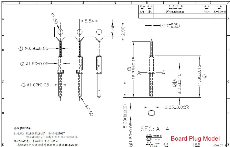
- DB1.0mm Male Pin for DB Terminal Connector Gold plated for Nixie Clock Tubes IN12 IN18 QS27-1 SZ4-1 YS27-3 - DB1.0mm Male pins used to insert into the 3D printed DB19 connector. If you can’t buy the you can pull them out of a DB25 connector.
- SPIISD DIY KIT - Another Arduino + SD Smartport based project. blog post
Other Apple //c related projects & articles
- Wozamp – an Apple II music and video player - Wozamp is a simple network music player for the Apple II
- The PLASMA Programming Language - PLASMA is a medium level programming language targeting the 8-bit 6502 processor. Documentation - YouTube playlist: Modern Retrogramming with PLASMA
- Reversing Choplifter - An article on the reverse engineering of the Choplifter game. Github repo with code.
- Prince of Persia disk images - FTP server with PoP disk images. github repo with the source code of Prince of Persia.
- Apple II Library: The 4am Collection = A huge library of Apple II games.
- Lode Runner (4am crack) - A cracked version of Lode Runner, my favorite Apple //c game. The ZIP file also contains a
.txtfile with 4am’s explenation of how the game was cracked. Very nice read. - Flight Simulator II v2.0 (woz-a-day collection - I used to play a lot this game on my Apple 2.
How to wire and use an ATMega328p microcontroller
While looking at Arduino related stuff I realized it might be useful to build a barebones ATMega328p based circuit for the final Arduino Apple //c project. I found a good video that show how simple the circuit is and a nice trick to be able to reprogram the chip using an Arduino Uno board. This is the video:
Build a Barebones ATMega328p Microcontroller Circuit / Forth