..
Week of the 06/10/2024 - #24
Contents
tech
- Apple //c Arduino drive
Apple //c Arduino drive
This week I did some additional research on how I can implement a floppy drive emulator on an Arduino to connect it to my Apple //c. Here are some of my notes on this:
- Peripheral cards with the Raspberry Pi Pico - Oliver Schmidt (KansasFest/A24eVR 2023) - This video re-ingnited my motivation to implement this. In the video they discuss at length how to hook up, in this case a Raspberry Pico to the address/data buses of an Apple 2. The author discusses several examples of boards and the intricacies of connecting these two very different type of computers.
- The video mentions how to handle the interface of buses that use different voltage levels. The Raspberry uses 3.3V while the Apple uses 5V. To be able to connect these two buses he uses SN74LVC245A - Octal Bus Transceiver With 3-State Outputs.
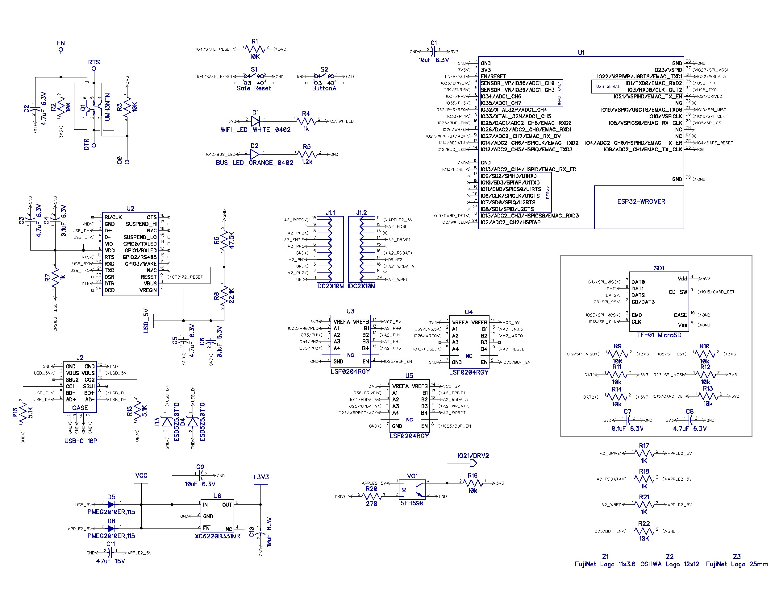
- Looking at the schematics in the Fujinet project they use a different (but related IC) to hook up the ESP-32 (3.3V logic) to the Apple 2: LSF0204x / 4-Bits Bidirectional Multi-Voltage Level Translator for Open-Drain and Push-Pull Application. From the datasheet: “The LSF family consists of bidirectional voltage level translators that operate from 0.8 V to 4.5 V (Vref_A) and 1.8 V to 5.5 V (Vref_B). This range allows for bidirectional voltage translations between 0.8 V and 5.0 V without the need for a direction terminal in open-drain or push-pull applications.”. This are surface mount devices so thery are tricky to connect. In the schematic these are U3, U4 and U5.
- Another very interesting piece of information mentioned in the video is how the Raspberry Pi can use the PIO controller to handle communication in the background. An Introduction to RP2040 PIO with CircuitPython - this article has a good beginner level discussion of how it works.
- Yet another interesting fact I learned is how the RP2024 (the IC that drives the Raspberry Pi) has the ability to load the firmware from a USB mass storage device. I find this feature very user friendly.
- The complications in matching the two TTL voltage levels convinced me that I will implement this on an Arduino so I went back to look at the ATmega328 datasheet (the microcontroller that is used in the Arduino devices) to see if there was some simpler way to transfer the data from the Arduino to the Apple 2c.
- Going through the datasheet I found two interesting options: Chapter 19. SPI – Serial Peripheral Interface and the, I think more promising Chapter 21 - 21. USART in SPI Mode
- In the later chapter it seems that what I need to use is the USART MSPIM Mode.
How information is stored on the Apple 2c disk
From the Beneath Apple DOS book archive.org and Understanding the Apple II:
- Apple formats its diskettes into 35 tracks.
- They are numbered from 0 to 34, track being the outermost track and track 34 the innermost.
- It should be pointed out, for the sake of accuracy, that the disk arm can position itself over 70 “phases” To move the arm past one track to the next, two phases of the stepper motor which moves the arm, must be cycled. This implies that data might be stored on 70 tracks, rather than 35.
- Although the standard DOS use only even phases, some protected disks use odd phases or combinations of the two, provided that no two tracks are closer than two phases from one another.
- DOS divides tracks into sectors.
- Each sector stores 256 bytes of data.
- Apple has used two different track format to date. One divides the track into 13 sectors, the other 16 sectors.
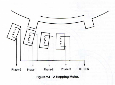
- To rotate the rotor one step to the right in Figure 9.4, energize the phase-2 magnet, then deenergize the phase-1 magnet. Magnetic attraction will then align the cog with the phase-2 magnet. To go three steps left from this new position, perform this progression: phase-1 on, phase-2 off, wait, phase-0 on, phase-1 off. wait, phase-3 on, phase-0 off, wait. The wait is for the response time of the motor, which is slow compared to the MPU. Summarizing, to step left, sequence through the phases in descending order. To step right, sequence in ascending order.
- Ascending references to $C080.X through $C087.X cause the head assembly on the enabled drive to move toward the inner track (track 34). Descending references cause movement toward track 0. The controlling program must wait approximately 20 milliseconds for motor response after turning a phase on.
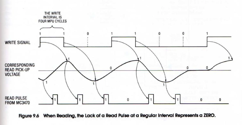
- When writing is not enabled, passing a field reversal on the surface of the disk over the read/write head induces a voltage in the coil. This induced voltage will alternate in polarity for every field reversal. The induced voltage is sensed by a special purpose chip which is designed for this function. The special purpose chip, a Motorola MC3470. outputs a positive one microsecond pulse for every field reversal (see Figure 9,6)
- The nuts and bolts details of disk I/O in most Apples are handled by the RWTS (Read or Write a TVack and Sector Subroutine) of the DOS
- In the absence of field reversals on the disk for too long, the read interface chip in the drive begins to generate invalid read pulses. You simply cannot read a long string of ZEROs, because your time reference is unstable and your read interface can’t do it anyway. How may ZEROs in a row can be read reliably? Two. In DOS 3.3, RWTS never writes more than two ZEROs in a row, and RWTS 3.2 never writes more than one ZERO in a row.
From the WOZ file format specification:
- While every track can be a different size, this is rarely the case. Just about all 5.25 floppy disk tracks will tend to each be 13 blocks long. Each block is 512 bytes so in all a track occupies 13 * 512 = 6144 bytes or 13 * 512 * 8 = 53248 bits.
- The bitstream data is the series of bits recorded from the floppy drive and normalized to 4µs intervals for 5.25 disks and 2µs for 3.5 disks. The bits are packed into bytes, but the bytes will not necessarily be representative of nibble values as timing bits are also represented within the bitstream.
- If you are creating a floppy drive emulator for use with a real Apple II, then you will simply be stepping to the next bit in the bitstream at the rate specified by the Optimal Bit Timing in the INFO chunk. If the bit has a 1 value, then you send a 1µs pulse on the RDDATA line. For a 3.5 drive, the pulse width would be 0.5µs.
Sample track 0, sector 0 of a track:

- Looking at the source of dsk2woz it’s simple to understand how tracks are layed out in DOS 3.3. The project is a single C file that has no dependencies. It taks a
.dskimage as input and generates a.wozfile. This is the meat of the routine that serializes a track:
// Write gap 1.
for(size_t c = 0; c < 16; ++c) {
    track_position = write_sync(dest, track_position);
}

// Step through the sectors in physical order.
for(size_t sector = 0; sector < 16; ++sector) {
    /*
        Write the sector header.
    */

    // Prologue.
    track_position = write_byte(dest, track_position, 0xd5);
    track_position = write_byte(dest, track_position, 0xaa);
    track_position = write_byte(dest, track_position, 0x96);

    // Volume, track, setor and checksum, all in 4-and-4 format.
    track_position = write_4_and_4(dest, track_position, 254);
    track_position = write_4_and_4(dest, track_position, track_number);
    track_position = write_4_and_4(dest, track_position, sector);
    track_position = write_4_and_4(dest, track_position, 254 ^ track_number ^ sector);

    // Epilogue.
    track_position = write_byte(dest, track_position, 0xde);
    track_position = write_byte(dest, track_position, 0xaa);
    track_position = write_byte(dest, track_position, 0xeb);


    // Write gap 2.
    for(size_t c = 0; c < 7; ++c) {
        track_position = write_sync(dest, track_position);
    }

    /*
        Write the sector body.
    */

    // Prologue.
    track_position = write_byte(dest, track_position, 0xd5);
    track_position = write_byte(dest, track_position, 0xaa);
    track_position = write_byte(dest, track_position, 0xad);

    // Map from this physical sector to a logical sector.
    const int logical_sector = (sector == 15) ? 15 : ((sector * (is_prodos ? 8 : 7)) % 15);

    // Sector contents.
    uint8_t contents[343];
    encode_6_and_2(contents, &src[logical_sector * 256]);
    for(size_t c = 0; c < sizeof(contents); ++c) {
        track_position = write_byte(dest, track_position, contents[c]);
    }

    // Epilogue.
    track_position = write_byte(dest, track_position, 0xde);
    track_position = write_byte(dest, track_position, 0xaa);
    track_position = write_byte(dest, track_position, 0xeb);

    // Write gap 3.
    for(size_t c = 0; c < 16; ++c) {
        track_position = write_sync(dest, track_position);
    }
}
Here’s a breakdown of the most important bits:
- The track starts with a group of 16 sync bytes. They are basically the following 10 bits repeated:
1111111100. This are, grouped in bytes:ff 3f cf f3 fc - For each sector we have the following 3 bytes which only appear as sector headers:
0xd5 0xaa 0x96 - After the sector header identifier there comes 4 integers encoded in whats called 4-and-4 format. Basically the binary number
D1 D2 D3 D4 D5 D6 D7 D8is encoded into two bytes1 D1 1 D3 1 D5 1 D7and1 D2 1 D4 1 D6 1 D8. To decode them you take the first number, rotate it once to the left andANDit with the second. This code you can see in the code that boots de first track. - These 4 numbers are: the volume, the track, the sector and the checksum.
- The sector header ends with the following 3 byte epilogue:
0xde 0xaa 0xeb - Then there are 7 sync bytes.
- Followed by the sector data prologue:
0xd5 0xaa 0xad - Then the sector data is enoded in whats called 6-and-2 format. The first 86 bytes contain shuffled and combined copies of the bottom two bits of the sector contents; the 256 bytes afterwards are the remaining six bits. There is one aditional byte that as a checksum to in total there are 343 bytes of sector data.
- Finally we have the 3 byte epilogue:
0xde 0xaa 0xeb - And a group of 16 more sync bytes finish the sector.
- Understanding this is important when you look at the boot code that is executed at address
$c600when a disk boots. - One important thing to point out is that if you look closely at the dump of sector 0, track 0 you will not find the data prologue (
0x45 0xaa 0xad). Why? Because what you are looking at is the bit stream and sync bytes are 10 bits long which shifts the secuence and breaks the alignment with bytes. To “fix” this you can modify thedsk2woz.cfile to output 8* sync bytes after the header instead of **7 and then you will be able to “see” the sector header.